Fiber Optic Cabinet Grounding & Lightning Protection: A Field Installation Guide
By Jergeo Engineering Team | Updated September 2026 · 12 min read
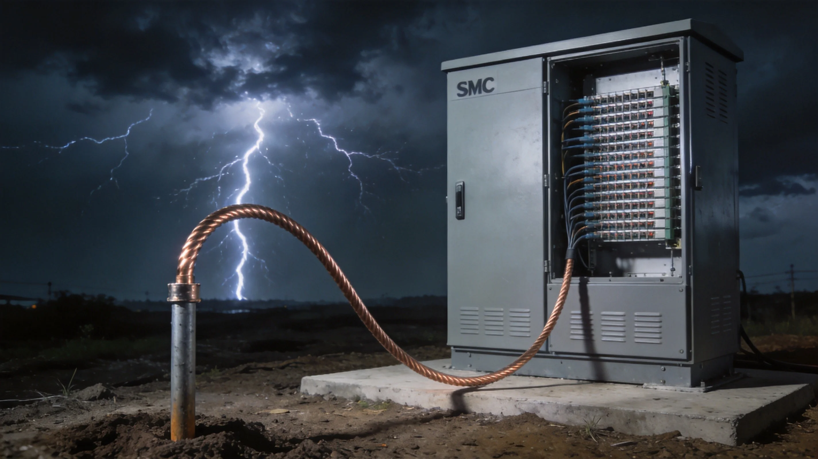
An outdoor fiber distribution cabinet that is not properly grounded is a liability. We have investigated enough lightning-damaged FDC installations to know that the failure is almost never the cabinet itself — it is the grounding system that was skipped, undersized, or installed incorrectly. Lightning does not need to hit the cabinet directly to cause damage. A strike within 500 meters induces a transient voltage surge that travels through the ground, up the grounding conductor (or through the earth if there is no proper conductor), and into the cabinet enclosure. Without a low-impedance path to earth, that energy finds the next available path — which usually means arcing across internal metal components, melting splice tray frames, or destroying fiber coatings at the point where metallic strength members enter the cabinet.
Here is the thing that surprises most field engineers: fiber optic cable does not conduct electricity. The glass fiber is a dielectric. So if fiber is non-conductive, why does grounding matter at all? Because the cable contains metallic strength members (steel wire or aramid yarn with metallic coatings), the cabinet shell is metal, and the environment exposes everything to electromagnetic transients from nearby strikes. The fiber itself survives — the infrastructure around it does not.
Summary
This guide covers fiber optic cabinet grounding and lightning protection from installation through maintenance. Topics include grounding resistance targets (below 5 ohms), the difference between grounding and bonding, step-by-step ground rod installation, surge protection device selection, and how enclosure material (steel vs SMC) affects the grounding approach. Applicable to outdoor FDC installations in all climates — tropical, temperate, and high-lightning-density regions.
Why Grounding Matters for Fiber Cabinets (Even Though Fiber Does Not Conduct)
This is the first question we get from field engineers who are new to outdoor fiber deployments. If the fiber is glass and does not conduct electricity, why spend time and money on a grounding system for the cabinet?
Three reasons.
First, the cable is not just fiber. Outdoor fiber optic cables contain metallic strength members — typically steel center strength wires or metallic aramid yarn coatings — that provide tensile strength during installation. These metallic elements enter the cabinet and are bonded to the grounding system. If lightning-induced voltage reaches the cable sheath or strength member without a path to ground, it arcs inside the cabinet at the entry point.
Second, the cabinet enclosure itself is conductive. Whether it is cold-rolled steel, galvanized steel, or SMC with internal metal reinforcement, the cabinet presents a large metallic surface exposed to the environment. A nearby lightning strike creates a voltage gradient in the soil. If the cabinet sits at a different potential than the surrounding earth, current flows — and the path it takes depends entirely on whether you have provided a proper grounding conductor.
Third, even if no fiber is damaged, a surge event can deform or melt the splice tray frame, corrode the grounding busbar at the connection point, or destroy the cabinet door seal through arcing. We have seen cabinets where the fiber survived but the mechanical structure was compromised — and the cabinet needed full replacement six months later when water ingress started corroding the fiber inside.
Grounding vs Bonding: Two Systems That Work Together
These terms get mixed up constantly. Here is the distinction that matters in the field:
Grounding is the connection between the cabinet and the earth. It uses a grounding conductor (copper wire, typically 6 AWG / 16 mm² or larger) that connects the cabinet grounding busbar to a ground rod driven into the soil. The purpose is to provide a low-impedance path for fault current and lightning energy to dissipate into the earth.
Bonding is the connection between all metallic parts within the cabinet — the door panel, the frame, the cable armor clamps, the metallic strength member of the incoming cable, the splice tray frame, and the grounding busbar itself. The purpose is to ensure all metal surfaces are at the same electrical potential, so no current flows between them during a surge event.
If you ground without bonding, you have a path to earth but internal components can still arc against each other. If you bond without grounding, everything is at the same potential but that potential might be thousands of volts above earth — and the first person to touch the cabinet completes the circuit to ground through their body. Grounding and bonding are both required for a safe installation.
Step 1: Determine the Required Grounding Resistance
The target for outdoor telecommunications cabinets is 5 ohms or less. This is consistent across IEEE Std 1100, IEC 62305, and most national telecommunications grounding standards. Some utilities specify 10 ohms for general installations, but for fiber distribution cabinets containing passive optical components, we recommend 5 ohms as the hard target.
Why 5 ohms? The lower the resistance, the faster and more completely the lightning current dissipates into the earth. At 5 ohms, a 10 kA surge produces a 50 kV potential at the ground rod — high, but the current has a clear path and dissipates in microseconds. At 50 ohms, that same surge produces 500 kV with slower dissipation, which means more energy looking for alternative paths — including through your equipment.
The soil resistivity at your installation site determines how difficult it is to reach 5 ohms. Rocky terrain, sandy soil, or permafrost can push natural soil resistivity above 1000 ohm-meters, making it challenging to achieve a low-resistance ground with a single rod. Here is what to do when the soil fights back:
- Multiple ground rods — drive two or three rods spaced at least 3 meters apart and connect them with buried copper conductor. Each additional rod reduces the total resistance, though not by half (mutual coupling reduces effectiveness).
- Chemical ground electrodes — these slow-release salt rods maintain a low-resistance column of electrolyte around the electrode, reducing resistance by 40-60% in high-resistivity soil. They need replacement every 3-5 years as the salt depletes.
- Ground enhancement material (GEM) — bentonite clay or carbon-based compounds packed around the ground rod reduce the effective soil resistivity. Bentonite absorbs moisture and maintains conductivity through dry seasons.
- Ground ring conductor — a bare copper conductor buried in a trench around the cabinet foundation, connected to the ground rod. This increases the earth contact surface area significantly and is the most effective solution for permanent installations.
Step 2: Install the Ground Rod and Grounding Conductor
The ground rod is the physical interface between your grounding system and the earth. Installation details matter.
- Rod specification — use a copper-clad steel rod, minimum 2.4 meters (8 feet) long and 16 mm (5/8 inch) diameter. Copper-clad provides the conductivity of copper with the mechanical strength of steel for driving. Solid copper rods bend when driven into compacted soil.
- Drive depth — the entire rod must be below the frost line. In tropical climates, 2.4 meters is sufficient. In temperate regions with frost depths of 1.2 meters or more, use a 3-meter rod or drive two overlapping rods. The rod tip should extend at least 300 mm below the frost line.
- Rod placement — position the ground rod within 1 meter of the cabinet base. The grounding conductor should run as straight and short as possible from the cabinet busbar to the rod. Every bend and every extra meter of conductor adds impedance, which reduces the effectiveness during a fast-rising lightning transient.
- Conductor specification — use stranded copper conductor, minimum 6 AWG (16 mm²). For high-lightning-density areas (more than 25 thunderstorm days per year), use 4 AWG (25 mm²) or larger. Route the conductor in a straight line from the busbar to the rod. Avoid sharp 90-degree bends — use gentle sweeping curves with at least 100 mm radius.
- Mechanical protection — where the grounding conductor runs along the cabinet exterior (from the busbar exit point down to the buried section), protect it with rigid PVC conduit or flexible metallic conduit. This prevents physical damage from lawn equipment, rodents, or accidental impacts during maintenance.
After driving the rod and connecting the conductor, measure the earth resistance with a calibrated 3-point earth resistance tester (fall-of-potential method). Record the measurement. If resistance exceeds 5 ohms, add a second rod or apply ground enhancement material before retesting.
Step 3: Bond All Internal Metallic Components
With the ground rod and conductor in place, the next step is to ensure every metallic surface inside the cabinet is bonded to the grounding busbar. This eliminates potential differences between components.
- Cabinet door and frame — use a braided copper bonding strap (not solid wire) between the door and the frame. Braided strap flexes with door movement without fatigue failure. Minimum width 16 mm.
- Cable armor and strength members — when the fiber cable enters the cabinet, strip the outer jacket and secure the metallic strength member to the grounding busbar using a cable gland with integrated grounding clamp or a separate grounding kit. This is the single most important bonding connection — it intercepts surge energy at the cable entry point before it reaches internal components.
- Splice tray frame — if the splice trays have a metal frame (most do), bond it to the grounding busbar with a short copper conductor. Some FDC designs use a grounded metal backbone that automatically bonds all trays when they are installed — verify this is connected.
- Cable entry glands — all metallic cable glands should be electrically continuous with the cabinet wall. Verify continuity with a multimeter after installation. Any gland that reads open circuit needs a bonding jumper.
The goal is simple: during a surge event, every metal surface in the cabinet should reach the same potential at the same time, and that potential should be close to earth potential because the grounding conductor provides the path. If any component floats to a different potential, you have an arc hazard.
Step 4: Install Surge Protection Devices (SPDs)
For passive fiber distribution cabinets, surge protection devices are not always necessary — the fiber itself does not carry electrical signals that need protecting. However, SPDs become critical in two situations:
Hybrid cabinets — if the FDC also houses active equipment (OLT, media converter, or powered splitter), the power supply input needs SPD protection. A Type 2 SPD rated for at least 40 kA (8/20 μs waveform) on the power input, combined with a Type 1 SPD at the service entrance, provides two-stage protection.
Cables with metallic strength members in high-lightning areas — even though the fiber does not conduct, the metallic strength member entering the cabinet carries surge energy from the external cable. Some operators install fiber optic surge protection units that clamp the metallic member to ground through a gas discharge tube, providing a controlled discharge path that protects the splice points inside the cabinet.
For standard passive FDC installations, the grounding and bonding system provides sufficient protection. SPDs add cost and maintenance requirements (they degrade over time and need replacement after major surge events). Install them when the risk profile justifies the investment — typically in areas with more than 40 thunderstorm days per year or where the cabinet houses expensive active equipment.
How Enclosure Material Affects Grounding Approach
The grounding principles are the same for all enclosure types, but the implementation details differ depending on whether your cabinet uses steel or SMC construction.
Steel cabinets (cold-rolled or galvanized) have a naturally conductive enclosure. The shell itself participates in the grounding system — if a surge strikes the cabinet exterior, the steel shell conducts current to the grounding busbar and down to the ground rod. This provides redundant paths and generally makes grounding easier to achieve.
SMC cabinets (Sheet Molding Compound — fiberglass-reinforced polyester) use a non-conductive shell. This provides superior corrosion resistance and dielectric isolation, but the grounding system must be entirely independent of the enclosure material. The internal metal frame, grounding busbar, and all bonding connections must form a complete system without relying on the shell for conductivity. The advantage: the non-conductive shell prevents external surge currents from coupling into the cabinet interior through the enclosure walls.
For the Jergeo FDC series, both the JFDC-288A (SMC construction) and larger models like the JFDC-576A and JFDC-1152A include a pre-installed grounding busbar and internal bonding points. The installer's job is to connect the ground rod conductor to this busbar, bond the incoming cable strength members, and verify continuity across all bonded components.
Lightning Protection Zones: Positioning the Cabinet
Grounding protects the cabinet, but positioning the cabinet in a lightning protection zone reduces the number of surge events it experiences in the first place.
The rolling sphere method (defined in IEC 62305-3) determines whether a structure is exposed to direct lightning strikes. A sphere of 20-60 meters radius (depending on the protection level) is rolled over the installation site. Any point the sphere touches is exposed; any point the sphere cannot reach is in a protection zone.
For ground-mounted FDC installations:
- If the cabinet is within the protection zone of a taller structure (building, tower, or existing lightning mast), the direct strike risk is significantly reduced. The cabinet still needs grounding for ground potential rise, but the surge energy it must handle is lower.
- If the cabinet stands alone in an open area — on a hilltop, alongside a highway, or in a field — it becomes the tallest point and the primary strike target. These installations require the full grounding treatment: ground rod, bonding, ground ring conductor, and consideration of a dedicated lightning mast positioned 3-5 meters from the cabinet.
- If the cabinet is pole-mounted, the pole itself may act as a partial shield for direct strikes, but it also conducts surge current down its length. Pole-mounted FDCs like the JFDC-72A and JFDC-144A must have the grounding conductor routed down the pole to a ground rod at the base, with the conductor mechanically protected along the entire pole length.
Maintenance: Testing the Grounding System Over Time
A grounding system that tested at 3 ohms on installation day can degrade to 30 ohms five years later if nobody checks it. Soil dries out, connections corrode, ground rods shift, and physical damage occurs. The system is invisible until it fails — and when it fails, it fails during a lightning event when you cannot inspect it.
Here is the maintenance schedule we recommend:
- Annual inspection (minimum) — visually check all connections for corrosion, verify the ground rod has not shifted, and measure earth resistance. Record the value and compare with the installation baseline. If resistance has increased by more than 50%, investigate and remediate.
- Pre-storm season check — in regions with distinct wet/dry or storm seasons, test grounding resistance before the high-risk period. Soil moisture changes can double or halve the resistance between seasons.
- Post-event inspection — after any confirmed lightning event within 1 km of the cabinet, perform a visual inspection. Look for scorch marks, melted bonding straps, displaced ground rod, or damaged cable entry glands. Replace any compromised components immediately.
- Coastal installations — salt spray accelerates copper corrosion. Check bonding straps and connections every 6 months. Apply anti-corrosion grease to exposed copper connections. Consider using tinned copper conductors instead of bare copper.
For high-value deployments — data center feeder points, hospital network nodes, or installations with more than 576 ports — consider installing a continuous ground monitoring system that alarms when resistance rises above threshold. The cost of monitoring is negligible compared to the cost of emergency restoration after a lightning failure.
Related Products
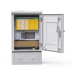
JFDC-72A Fiber Distribution Node
72-port compact FDC for pole-mount and ground-mount — ideal for edge-of-network deployments requiring lightning protection.
View Product →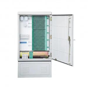
JFDC-288A Fiber Distribution Cabinet
288-port SMC FDC with IP65 protection, pre-installed grounding busbar, and drawer-type splice trays.
View Product →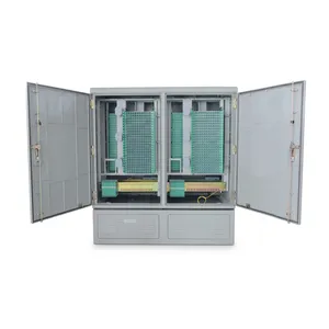
JFDC-1152A Fiber Distribution Cabinet
1152-port high-capacity FDC with 24-module frame — designed for large aggregation points with comprehensive grounding infrastructure.
View Product →Related Articles
Fiber Distribution Cabinet Buying Guide
Capacity planning, material selection, and IP rating for FDC procurement decisions.
Read Article →
Pole Mount Cabinet Installation Guide
Step-by-step pole mounting instructions including grounding conductor routing down the pole.
Read Article →
The Evolution of Fiber Distribution Cabinets
How FDC design has evolved from simple metal boxes to intelligent enclosures with integrated grounding and monitoring.
Read Article →References
Key takeaway
Fiber optic cabinet grounding is not optional — it is the single most important installation practice that determines whether your FDC survives its first lightning season intact. Ground the cabinet below 5 ohms. Bond every metallic component inside. Connect the cable strength members to the grounding busbar at the entry point. Test the system annually and after every major storm. The cost of a proper grounding system is less than 2% of the cost of replacing a lightning-damaged cabinet and re-splicing 288 fibers in the rain.
Related products