Optical Distribution Frame (ODF)
The indoor backbone of every central office and data center — where thousands of fibers converge, splice, and cross-connect on open racks.
An optical distribution frame (ODF) — also called a fiber distribution frame, fiber patch panel rack, or optical cross-connect frame — is an open-frame or semi-enclosed rack that provides structured fiber management inside a central office, data center, or telecom room. Unlike outdoor FDCs that seal fibers inside a weatherproof cabinet, an ODF sits in a controlled indoor environment and prioritizes density, accessibility, and cable routing order over weather protection.
Jergeo manufactures seven ODF models across three series. Series A (JODF-A1, JODF-A2) uses an open-frame design with top-and-bottom cable entry. Series B (JODF-B1, JODF-B2) adds independent wiring channels between modules for cleaner maintenance. Series C (JODF-C1, JODF-C2, JODF-C3) uses a center-mounted bobbin layout for symmetrical fiber routing. All models use cold rolled steel construction, standard 19-inch rack mounting, and integrated splice-and-distribution modules. Fiber capacity ranges from 432 to 1440 ports per frame. Insertion loss is \u22640.2 dB per mated pair.
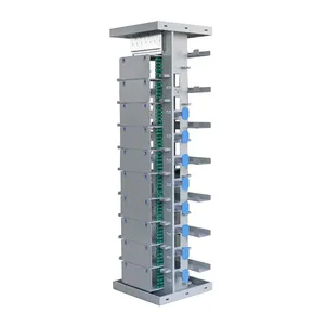
JODF-A1 Optical Distribution Frame
Optical distribution frame with 720 ports, 42U capacity. Cold rolled steel, 19-inch rack, ≤0.2dB insertion loss. Factory direct, OEM/ODM, MOQ from 1.
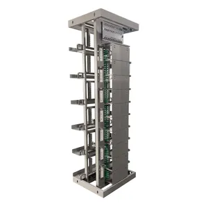
JODF-A2 Optical Distribution Frame
Optical distribution frame with 720 ports and larger dimensions. Cold rolled steel, 19-inch rack. FC/SC/LC adapters. Factory direct, OEM/ODM, MOQ from 1.
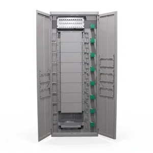
JODF-B1 Optical Distribution Frame
Optical distribution frame, 720 ports with independent wiring channels. Cold rolled steel, 19-inch rack. Factory direct, OEM/ODM, MOQ from 1.
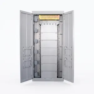
JODF-B2 Optical Distribution Frame
1008-port high-capacity optical distribution frame. Cold rolled steel, 19-inch rack, ≤0.2dB insertion loss. Factory direct, OEM/ODM, MOQ from 1.
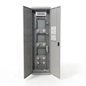
JODF-C1 Optical Distribution Frame
432-port optical distribution frame with central bobbin design. Cold rolled steel, 19-inch rack. Factory direct, OEM/ODM, MOQ from 1.
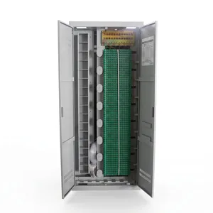
JODF-C2 Optical Distribution Frame
1440-port ultra high-capacity optical distribution frame. Cold rolled steel, 19-inch rack, ≤0.2dB insertion loss. Factory direct, OEM/ODM, MOQ from 1.
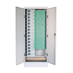
JODF-C3 Optical Distribution Frame
672-port optical distribution frame with compact design. Cold rolled steel, 19-inch rack. FC/SC/LC adapters. Factory direct, OEM/ODM, MOQ from 1.
An ODF Is Not an Indoor FDC — The Difference Is Structural, Not Environmental
ODF vs FDC — Indoor Open Frame vs Outdoor Sealed Cabinet
It is tempting to think of an ODF as "an FDC for indoor use." They both splice fibers and distribute them through adapter ports. But the structural difference between an open frame and a sealed cabinet changes everything about how you plan, install, and maintain the fiber infrastructure.
| ODF | FDC | |
|---|---|---|
| Environment | Indoor (central office, data center, equipment room) | Outdoor (street, building exterior) |
| Structure | Open frame or semi-enclosed rack | Sealed cabinet with door gaskets |
| Weather protection | Not needed (controlled environment) | IP65 required |
| Capacity | 432–1440 ports per frame | 72–1152 ports per cabinet |
| Cable entry | Top and bottom of rack | Bottom pedestal |
| Access | Open front and rear, walk-around | Front door(s), some with rear door |
| Module type | Integrated splice-and-distribution module | Drawer-type splice-and-distribution module |
| Expandability | Add another frame side by side | Add another cabinet (requires pad space) |
The critical practical difference: an ODF has no door between you and the fibers. You walk up to the rack, and every module, every splice tray, every adapter port is right there. No door to open, no seal to maintain, no weatherproofing to worry about disturbing. This means faster installation, faster troubleshooting, and faster changes — but only in an environment where the air is clean, the temperature is controlled, and nobody is going to hose down the room.
An ODF also scales differently. When you run out of ports on an FDC, you install a second cabinet — which means a second concrete pad, a second cable run, a second weather seal to maintain. When you run out of ports on an ODF, you install another frame right next to it and run a trunk cable between them. In a data center with rows of ODFs, this is routine. On a street corner, it is a construction project.
When to use which
- Central office, CO, headend, data center, equipment room: ODF. Always. An FDC indoors is wasted money on weatherproofing you do not need.
- Outdoor street cabinet, building exterior: FDC. An ODF outdoors will not survive the first rainstorm.
- Indoor but high-density campus hub: ODF. The density and accessibility advantages are significant when you are managing hundreds of fiber connections.
The Difference Is Not the Port Count — It Is How Fibers Get from the Splice to the Adapter
Series A, B, and C — Three Wiring Philosophies
All seven Jergeo ODFs use the same core components: cold rolled steel frame, 19-inch rack rails, integrated splice-and-distribution modules, FC/SC/LC adapters. The difference between Series A, B, and C is the internal cable routing philosophy — how fibers are managed between the splice point and the adapter port.
Series A — Open Frame (JODF-A1, JODF-A2)
The simplest design. Modules are mounted on the rack rails. Fibers route from the splice trays directly to the adapter ports through open cable management channels. There are no separate wiring ducts — everything shares the same vertical space.
- Advantage: Maximum visibility. Every fiber run is visible, which makes troubleshooting fast.
- Limitation: In a fully loaded 720-port frame, adding a new fiber run means routing it around existing ones. Requires cable management discipline.
- Best for: Central offices with experienced technicians. Also the most compact option — JODF-A1 at 550×550mm fits in tight equipment rooms.
Series B — Independent Wiring Channels (JODF-B1, JODF-B2)
Each module row has its own horizontal wiring channel. Fibers from the splice trays in that row route through the dedicated channel to the adapter ports, without crossing into other rows' channels. This physical separation means working on row 3 does not disturb fibers in row 1.
- Advantage: Maintenance isolation. You work within one channel without touching others. Matters in 24/7 central offices where you cannot take the entire frame offline.
- Limitation: Wider frame. The independent channels add width — JODF-B1 is 840mm wide vs. 550mm for JODF-A1.
- Best for: Active central offices where live fiber changes happen regularly and disturbing adjacent connections is not acceptable.
Series C — Center Bobbin (JODF-C1, JODF-C2, JODF-C3)
The splice-and-distribution modules are arranged on both sides of a central fiber management bobbin. Fibers from the left-side modules route through the center bobbin to the right-side adapter ports, and vice versa. This symmetrical layout means cable lengths are equal on both sides, which simplifies fiber management and reduces slack.
- Advantage: Equal fiber lengths and organized slack management. The center bobbin stores excess fiber length neatly — important for future re-splicing.
- Limitation: Depth is fixed by the bobbin diameter. C-series frames are 300–600mm deep.
- Best for: High-density applications. The JODF-C2 at 1440 ports is the highest-density ODF in the Jergeo line — 120 modules in a single frame.
| Priority | Choose | Why |
|---|---|---|
| Smallest footprint | JODF-A1 (550×550mm) | Narrowest and shallowest frame |
| Highest density | JODF-C2 (1440 ports) | 120 modules in one frame |
| Maintenance isolation | JODF-B1 or B2 | Independent wiring channels per row |
| Balanced capacity/size | JODF-A2 (720 ports, 720mm wide) | More working space than A1, same capacity |
| Medium density with bobbin | JODF-C3 (672 ports) | Center bobbin in a shorter frame (1900mm) |
One Module = 12 Fibers. Every ODF Is Just a Stack of These.
Splice-and-Distribution Modules — The Building Block of Every ODF
All Jergeo ODFs use integrated splice-and-distribution modules. Each module handles 12 fibers and combines three functions in one unit:
The rear section holds splice sleeves where incoming fibers are fusion-spliced to pigtails.
The middle section manages fiber bend radius and stores slack.
The front section terminates pigtails on adapter ports (FC, SC, or LC).
This three-in-one design is why ODFs can achieve such high density. A traditional setup uses separate splice trays, fiber routing panels, and adapter panels — each taking up rack space independently. The integrated module does all three in the space of a single 1U adapter panel.
| Model | Ports | Modules | Rack Space per Module |
|---|---|---|---|
| JODF-A1 | 720 | 60 | ~0.7U each |
| JODF-A2 | 720 | 60 | ~0.7U each |
| JODF-B1 | 720 | 60 | ~0.7U each |
| JODF-B2 | 1008 | 84 | ~0.5U each |
| JODF-C1 | 432 | 36 | ~1.2U each |
| JODF-C2 | 1440 | 120 | ~0.35U each |
| JODF-C3 | 672 | 56 | ~0.75U each |
The JODF-C2 packs 120 modules into a 42U frame — an average of 0.35U per module, or about 15mm of vertical space per module. This is achievable because the center bobbin layout eliminates the need for separate cable management between modules.
Adapter options and durability
- Adapter types per module: FC, SC, or LC. Configured per module at order time. You can mix adapter types within the same frame — SC/APC for PON, LC/UPC for data center interconnects.
- Durability: All modules rated for >1000 mating cycles per adapter port (IEC 61753-1). A cheap adapter that fails after 200 cycles will cost you in truck rolls and service interruptions long before the frame reaches end of life.
Related Solutions
See how ODFs organize fiber infrastructure in data centers
Explore Data Center Solution