Fiber Splice Tray
The tray that holds every fusion splice — the most touched component inside every FDC, splice closure, and ODF.
A fiber splice tray is a molded plastic or metal tray that secures fusion splice sleeves, stores fiber slack, and maintains minimum bend radius at every splice point. It is the internal component that every field technician opens when adding, modifying, or repairing a fiber splice. If the splice sleeve is the joint, the splice tray is the joint protector — and if the tray does not hold the fiber at the correct bend radius, the splice will fail from macro-bend loss even though the fusion itself was perfect.
Jergeo manufactures fiber splice trays in four capacities: 12-core, 24-core, 36-core, and 48-core. These trays ship as standard accessories inside Jergeo FDCs, fiber splice closures, optical terminal boxes, ODFs, and patch panels. They are also available as standalone replacement parts. The JZR-A direct splice tray (160x100x12mm) is designed for splicing-only applications where adapter termination is handled elsewhere.
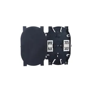
JST-A Splice Tray
Fiber splice tray, 12-core, ABS material. 30mm minimum bend radius, stackable. For FDCs, closures, and ODFs. Direct manufacturer, MOQ from 1.
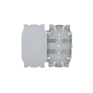
JST-B Splice Tray
Fiber splice tray, 24-core, ABS material. 30mm minimum bend radius, stackable. For FDCs, closures, and ODFs. Direct manufacturer, MOQ from 1.
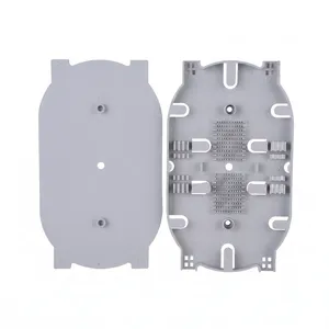
JST-C Splice Tray
Fiber splice tray, 36-core, ABS material. 30mm minimum bend radius, stackable. For FDCs, closures, and ODFs. Direct manufacturer, MOQ from 1.
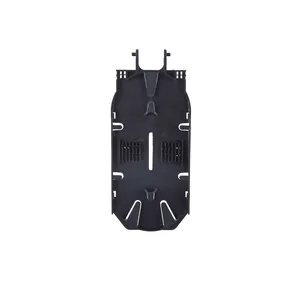
JST-D Splice Tray
Fiber splice tray, 48-core, ABS material. 30mm minimum bend radius, stackable. For FDCs and ODFs. Direct manufacturer, MOQ from 1.
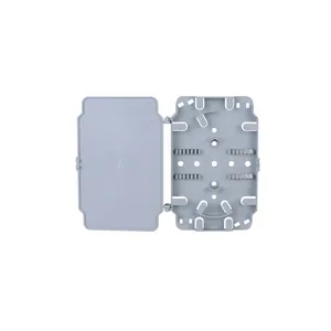
JST-E Splice Tray
Fiber splice tray, 12-core, PC material. 30mm minimum bend radius, hinged design. For closures and ODFs. Direct manufacturer, MOQ from 1.
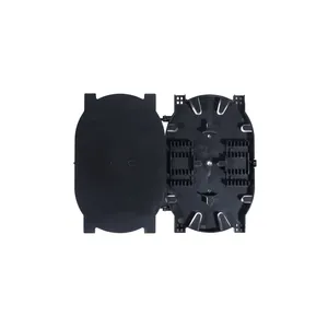
JST-F Splice Tray
Fiber splice tray, 24-core, PC material. 30mm minimum bend radius, hinged design. For closures and ODFs. Direct manufacturer, MOQ from 1.
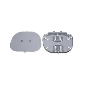
JST-G Splice Tray
Fiber splice tray, 36-core, PC material. 30mm minimum bend radius, hinged design. For FDCs and closures. Direct manufacturer, MOQ from 1.
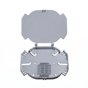
JST-H Splice Tray
Fiber splice tray, 48-core, PC material. 30mm minimum bend radius, hinged design. For FDCs and ODFs. Direct manufacturer, MOQ from 1.
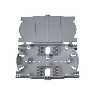
JST-I Splice Tray
Compact fiber splice tray, 12-core, ABS. 157.5×101×12mm, 30mm min bend radius. For FDB and FDC enclosures. Direct manufacturer, MOQ from 1.
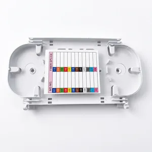
JST-J Splice Tray
Fiber splice tray, 12-core, ABS. 220×108×12mm, 30mm min bend radius. For FDB and FDC enclosures. Direct manufacturer, MOQ from 1.
One Does Splicing Only. The Other Does Splicing Plus Termination.
Confuse Them and You Order the Wrong Part.
The single most common point of confusion in ODN component ordering is the difference between a splice tray and a splice-and-distribution module (SDM). They are not interchangeable.
A fiber splice tray does exactly one thing: it holds fusion splice sleeves and stores the fiber slack. Period. There are no adapter ports on a splice tray. The fibers come in, get fusion-spliced inside the tray, and the splice sleeves sit in the tray's retaining grooves. The output fibers (pigtails) exit the tray and go to an adapter panel elsewhere in the enclosure.
A splice-and-distribution module (JSDM series) does three things: it holds fusion splices (like a splice tray), stores fiber slack (like a splice tray), and terminates the pigtails on adapter ports at the front face (unlike a splice tray). An SDM is a self-contained cassette — splice zone + storage + adapter plate in one pull-out unit.
Why both exist: In small enclosures — a fiber splice closure (FSC) or an optical terminal box (OTB) — the splice tray and the adapter panel are separate components inside the same box. The tray sits below or behind the adapter panel, and the pigtail routes between them. In large enclosures — an FDC or ODF — the SDM integrates all three functions into one module because you need to manage hundreds of fibers and you cannot afford the space of separate trays and panels.
| What You Need | Order This | Why |
|---|---|---|
| Replacement tray for a splice closure (FSC) | Fiber Splice Tray (12/24/36/48 core) | FSCs use separate trays and adapters |
| Replacement tray for an OTB | Fiber Splice Tray | OTBs use separate trays — adapter plate is a different part |
| Replacement module for an FDC drawer | Splice-and-Distribution Module (JSDM) | FDCs use integrated SDMs, not standalone trays |
| Replacement module for an ODF shelf | Splice-and-Distribution Module (JSDM) | ODFs use integrated SDMs |
| Just need to splice, adapters handled elsewhere | JZR-A Direct Splice Tray | Splicing only — smallest, simplest option |
Every Enclosure Has a Maximum Tray Count
And You Hit It Faster Than You Think
A fiber splice tray is not a standalone product. It lives inside an enclosure. The enclosure dictates how many trays fit, what capacity each tray can be, and how you access the trays for maintenance. Get the count wrong and you cannot close the box.
| Enclosure | Max Trays | Tray Capacity | Total Splice Capacity |
|---|---|---|---|
| FSC (dome, 144-core) | 6 or less | 24 cores/tray | 144 fibers |
| FSC (large, 288-core) | 4 or less | 36 cores/tray | 144 fibers |
| OTB (192-core) | 8 or less | 24 cores/tray | 192 fibers |
| OTB (48-core, metal) | 2 or less | 24 cores/tray | 48 fibers |
| OTB (small, 12-core) | 1 | 12 cores/tray | 12 fibers |
| FDC (all models) | Uses SDMs instead of standalone trays | ||
| Patch Panel (1U-6U) | 1-2 | 24 cores/tray | 24-48 fibers |
Stackable (fixed-mount): Each tray sits on a fixed rail. To access a lower tray, you must remove the upper trays. Common in FSCs. Simpler mechanical design but more handling during maintenance.
Hinged (flip-up): Each tray is mounted on a hinge or pivot. You flip the upper tray up to access the one below, without removing it. Common in ODFs and some OTBs. Better for frequent maintenance but more complex mechanically.
A Perfect Splice in a Bad Tray Still Fails
The 30mm Bend Radius Is Not a Suggestion — It Is the Difference Between Working and Not Working
Every fiber inside a splice tray must maintain a minimum bend radius of 30mm (for G.652D single-mode fiber per ITU-T G.652). This is not a recommendation — it is a physical limit. Below 30mm, the fiber suffers macro-bend loss: light leaks from the core at the tight bend, and the insertion loss increases. The splicer reports a perfect splice (0.01 dB), but the fiber after the splice — routed through the tray — has 1 dB or more of additional loss from macro-bending.
Why this is hard to diagnose: Macro-bend loss shows up on an OTDR trace as a non-reflective event (a dip, not a spike) at the splice point. It is one of the hardest fiber faults to diagnose in the field because the fusion splice itself tests fine, but the tray routing kills the signal.
How Jergeo splice trays prevent it: All fiber routing channels in Jergeo splice trays are molded with 30mm or greater bend radius at every corner. The splice sleeve retaining grooves, the fiber slack storage area, and the cable entry/exit ports are all designed to keep the fiber above the minimum bend radius — even when the tray is fully loaded with 24 or 48 splice sleeves.
The JZR-A exception: The JZR-A direct splice tray (160x100x12mm) is only 12mm tall. At this height, there is no room for fiber slack storage. The JZR-A is designed for short pigtail runs where the spliced fiber routes directly to an adjacent adapter panel — the excess fiber is stored in the panel area, not in the tray. Do not use the JZR-A for long pigtail runs that require fiber coiling inside the tray.
Related Solutions
See splice tray applications in outdoor cable joints
Explore Outdoor Deployment Solution