Fiber Distribution Box (FDB)
The last split before the subscriber — where PLC splitters turn one feeder fiber into dozens of drop connections.
A fiber distribution box (FDB) sits downstream of the fiber distribution cabinet (FDC) and upstream of the terminal box. Its job is straightforward: receive a small number of feeder fibers from the FDC, run them through PLC splitters, and deliver drop cables to individual subscribers. In most FTTH architectures, this is the enclosure that actually holds the splitter — the FDC handles splicing and cross-connect, but the FDB does the splitting.
Jergeo manufactures FDBs from 12 to 96 ports in SMC, ABS, and PC+ABS. All models are wall-mount or pole-mount — no ground-mount option, because these boxes serve a small coverage area (typically one building or one pole location) and need to be compact. Every outdoor model is IP65 rated and operates from -45\u00b0C to +65\u00b0C. Internal configurations support both splitter-based (LGX module slots) and pre-terminated (direct adapter termination) designs.
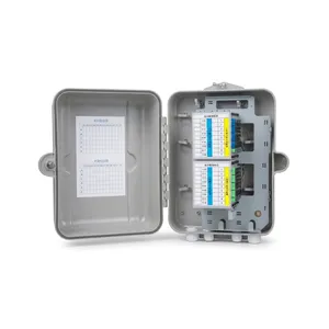
JFDB-64A Fiber Distribution Box
Fiber distribution box with 64 ports, SMC material and integrated PLC splitter. IP65, wall or pole mount. Factory direct, OEM/ODM, MOQ from 1.
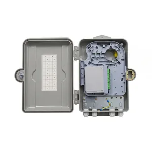
JFDB-16C Fiber Distribution Box
Compact 16-port fiber distribution box with SMC material. IP65, built-in splitter slot, wall or pole mount. Factory direct, OEM/ODM, MOQ from 1.
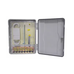
JFDB-96A Fiber Distribution Box
High-capacity 96-port fiber distribution box with ABS material. IP65, built-in PLC splitter slots. Wall or pole mount. Factory direct, OEM/ODM, MOQ from 1.
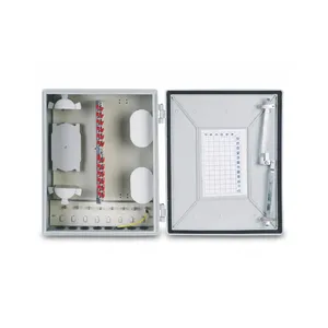
JFDB-48B Fiber Distribution Box
48-port fiber distribution box with SMC material. IP65, built-in splitter slots, wall or pole mount. Factory direct, OEM/ODM, MOQ from 1.
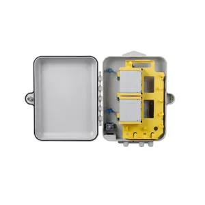
JFDB-32A Fiber Distribution Box
32-port fiber distribution box with dual-layer design. SMC, IP65, splitter-compatible. Wall or pole mount. Factory direct, OEM/ODM, MOQ from 1.
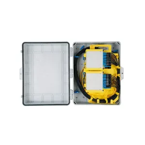
JFDB-32B Fiber Distribution Box
Lightweight 32-port fiber distribution box with PC+ABS material. IP65, dual-layer, wall or pole mount. Factory direct, OEM/ODM, MOQ from 1.
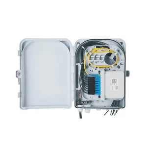
JFDB-24A Fiber Distribution Box
Compact 24-port fiber distribution box with multiple splitter options. SMC, IP65, wall or pole mount. Factory direct, OEM/ODM, MOQ from 1.
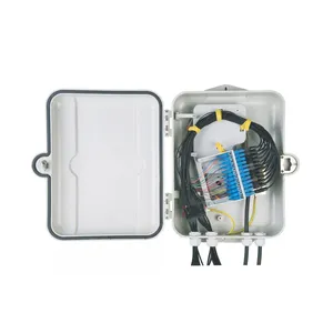
JFDB-16A Fiber Distribution Box
16-port fiber distribution box with SMC material and dual-layer design. IP65, built-in splitter slot. Wall or pole mount. Factory direct, OEM/ODM, MOQ from 1.
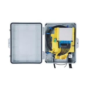
JFDB-16B Fiber Distribution Box
Lightweight 16-port fiber distribution box with PC+ABS material. IP65, dual-layer, wall or pole mount. Factory direct, OEM/ODM, MOQ from 1.
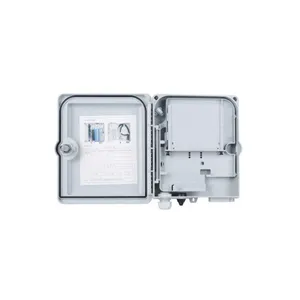
JFDB-12A Fiber Distribution Box
Compact 12-port fiber distribution box with PC+ABS material. IP65, splitter-compatible, wall or pole mount. Factory direct, OEM/ODM, MOQ from 1.
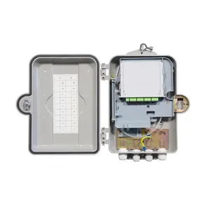
JFDB-12B Fiber Distribution Box
12-port fiber distribution box with SMC material. IP65, built-in splitter slot, wall or pole mount. Factory direct, OEM/ODM, MOQ from 1.
The Split Happens Here — And That Changes Everything About How You Size It
Where the FDB Fits in the ODN Chain
The signal path in a typical FTTH network looks like this:
The FDC receives the feeder cable, splices fibers, and routes them to distribution cables. The FDB receives those distribution cables and runs the fibers through PLC splitters. That is the critical difference: the FDC is a cross-connect point; the FDB is a split point.
This distinction matters for two reasons:
1. The splitter ratio determines your subscriber reach.
A 1×8 PLC splitter turns one input fiber into 8 output fibers. A 1×16 splitter turns one into 16. So a 32-port FDB with four 1×8 splitters serves up to 32 subscribers using only 4 feeder fibers from the FDC. Without splitters, you would need 32 feeder fibers — which means a bigger FDC, more cable, and more splicing labor. The splitter is what makes FTTH economical at scale.
2. The splitter insertion loss eats your optical budget.
Every split costs dB. A 1×8 PLC splitter has approximately 10.8 dB insertion loss (theoretical 9.03 dB per ITU-T G.671, plus connector and manufacturing tolerance). A 1×16 splitter costs approximately 13.5 dB. This is not a rounding error — it is the single largest loss contributor in the drop segment. When you choose between a 1×8 and a 1×16 configuration in the same FDB, you are not just deciding how many subscribers to serve. You are deciding how much optical budget is left for the drop cable run to the ONT.
This is why Jergeo FDBs offer both splitter-based and adapter-based (pre-terminated) internal configurations. In splitter mode, the box houses LGX PLC splitter modules with SC adapters on the output face. In pre-terminated mode, pigtails are fusion-spliced directly and terminated on adapter holders — no splitters, lower loss, but limited to the number of feeder fibers you bring in. Your network architecture decides which mode you need; the box should support both.
Three Materials, Three Price Points, Three Use Cases
Pick Based on Where the Box Hangs
FDBs are smaller and lighter than FDCs, and they hang on walls or poles instead of standing on the ground. That means the material choice is driven by different factors. Here is the practical breakdown.
SMC (Glass-Fiber Reinforced Polyester)
- Does not corrode. No rust, ever. UV-stable when properly formulated.
- Heavier than ABS or PC+ABS at the same port count. A JFDB-32A (SMC) weighs more than a JFDB-32B (PC+ABS) at identical dimensions.
- Best long-term thermal stability. SMC maintains mechanical properties across the full -45°C to +65°C range without becoming brittle in cold or softening in heat.
- Operating range: -45°C to +65°C.
Best for:
Pole-mounted deployments where the box is exposed to full weather for 15+ years, or any project where the spec calls for SMC-equivalent material.
PC+ABS (Polycarbonate + ABS Blend)
- Lighter than SMC at the same size. Easier to handle on a pole or wall bracket — one person can install it without a helper.
- Good impact resistance. PC+ABS absorbs knocks and vibration better than SMC, which matters for pole-mounted boxes that get bumped by maintenance crews or sway in wind.
- Lower material cost than SMC. Typically 20–30% less at the same dimensions.
- Operating range: -45°C to +65°C. In sustained ambient temperatures above 55°C (direct sun on a dark surface), PC+ABS may begin to show surface discoloration before SMC does.
Best for:
Wall-mounted deployments on building facades where weight matters, mild to moderate climates, and projects where unit cost is a primary driver.
ABS (Acrylonitrile Butadiene Styrene)
- The lightest option. Used in the JFDB-96A — the highest-port FDB — because the 550×415×150mm size would be prohibitively heavy in SMC for a wall/pole mount.
- Good impact resistance, adequate for sheltered outdoor locations.
- Lower UV resistance than SMC or PC+ABS unless a UV-stabilized grade is specified. In direct tropical sun without shade, ABS may yellow and become brittle faster.
- Operating range: -45°C to +65°C.
Best for:
High-port-count applications (64+ ports) where weight is the binding constraint, or indoor/outdoor sheltered locations.
The Decision Matrix
| Deployment | Material | Why |
|---|---|---|
| Pole, exposed, 15+ year spec | SMC | Longest service life, no UV degradation, no corrosion |
| Wall, building facade, moderate climate | PC+ABS | Lighter install, lower cost, adequate durability |
| High-port-count, weight-limited mount | ABS | Only way to get 96 ports into a wall-mount box |
| Coastal or industrial zone | SMC | Chemical and salt resistance exceeds PC+ABS and ABS |
One Splitter Choice Costs You 3 dB — Here Is How to Calculate the Trade-Off
Splitter Configuration — The Math That Determines Your Network Design
The PLC splitter inside the FDB is not an afterthought. It is the component that determines how many subscribers one box can serve and how far those subscribers can be from the box. Get the splitter ratio right, and your optical budget works with margin. Get it wrong, and you are explaining to the customer why the ONT at the end of the street keeps dropping offline.
Splitter Insertion Loss (typical values per ITU-T G.671)
| Splitter Ratio | Theoretical Loss | Typical Insertion Loss (with connectors) |
|---|---|---|
| 1×4 | 6.02 dB | 7.5 dB |
| 1×8 | 9.03 dB | 10.8 dB |
| 1×16 | 12.04 dB | 13.5 dB |
| 1×32 | 15.05 dB | 17.0 dB |
* Actual loss varies by manufacturer grade (Grade A/B/C) and connector type. Values above are for Grade A PLC splitters with SC/APC connectors, which is what Jergeo supplies as standard.
Pick 1×16 when:
You have limited feeder fibers available. One input fiber serves 16 subscribers. The trade-off is 2.7 dB more insertion loss (13.5 dB vs 10.8 dB), which reduces the maximum drop cable length by roughly 8–10 km at 1310nm (assuming G.652.D fiber at ~0.35 dB/km). If your subscribers are all within a single building or a short drop run, the extra loss is acceptable.
Pick 1×8 when:
You have more feeder fibers available and want longer drop cable reach. Two input fibers serving 16 subscribers gives you 2.7 dB more optical budget per subscriber — that translates to roughly 8 km more reach on the drop side. Use this for suburban pole-mounted deployments where drop cables may run 1–3 km.
Quick Reference for Jergeo FDB Configurations
| Model | Splitter Setup | Input Fibers | Output Ports | Total Splitter Loss |
|---|---|---|---|---|
| JFDB-64A | 1×8 × 8 | 8 | 64 | 10.8 dB each |
| JFDB-32A/B | 1×8 × 4 | 4 | 32 | 10.8 dB each |
| JFDB-24A (Type 1) | 1×16 × 1 | 1 | 16 | 13.5 dB |
| JFDB-24A (Type 2) | 1×8 × 2 | 2 | 16 | 10.8 dB each |
| JFDB-16A/B/C | 1×8 × 2 | 2 | 16 | 10.8 dB each |
| JFDB-12A/B | 1×8 × 1 | 1 | 8 | 10.8 dB |
The JFDB-96A and JFDB-48B use adapter-based (pre-terminated) configurations without internal splitters — they terminate feeder fibers directly on adapter holders. Use these when your splitter is located elsewhere in the network (e.g., a splitter module inside the FDC), or when you are running a point-to-point architecture without passive splitting.
Where an FDB Actually Serves Subscribers — Four Scenarios That Matter
Common Applications — Pick the Box to Match the Deployment
Not every FDB installs the same way, and the wrong box for the deployment is the most common field mistake we see. Here is how the four highest-volume FDB scenarios map to Jergeo models.
1. FTTH Drop Point — Residential Street Cabinet
The classic last-mile fix. A feeder from the local FDC terminates here, and 1×8 or 1×16 PLC splitters fan out to 16–64 homes on a multi-dwelling or single-family block.
Best fit: JFDB-16B / JFDB-32B (PC+ABS, wall or pole)
2. FTTH High-Density — Multi-Unit Buildings (MDU)
Inside or outside an apartment block serving many subscribers from one drop point. The box handles more ports and often a mix of splitters and direct terminations.
Best fit: JFDB-64A (SMC, high density, 1×8 × 8)
3. Rural / Suburban Long-Reach Drop
Feeder fiber is scarce and drop cables must stretch 1–3 km. A 1×8 configuration preserves optical budget (only 10.8 dB loss) for long pigtail runs to the ONT.
Best fit: JFDB-12A / JFDB-24A (Type 1, 1×16 or single-input)
4. Point-to-Point / No-Split Feeder
Your splitter lives upstream (e.g., inside the FDC) or you run a non-PON architecture. Terminate feeder fibers directly on adapters — no internal splitter, lowest possible loss.
Best fit: JFDB-48B / JFDB-96A (adapter-based, pre-terminated)
The golden rule: match the FDB to where it hangs (material and mounting) and to how many subscribers it serves (splitter ratio and port count). Change the splitter layout and you change the box model — that is exactly why Jergeo offers both splitter-based and pre-terminated internal configurations across the FDB range, with MOQ from 1 and 1-hour response for custom ratios.
Related Solutions
See how FDBs integrate into FTTH last-mile distribution
Explore FTTH Network Solution