Fiber Optic Patch Panel
The rack-mount termination point where fibers enter a 19-inch frame, get spliced, organized, and connected — compact, modular, and designed for equipment rooms.
A fiber patch panel (also called an optical patch panel or ODF unit) is a 19-inch rack-mount enclosure that terminates incoming fiber cables, organizes splices and patch connections, and presents adapter ports on its front face. Unlike floor-standing ODF frames that serve as standalone distribution nodes, a patch panel slides into a standard 19-inch equipment rack alongside switches, servers, and other active gear. It is the smallest managed fiber termination unit in the ODN chain — and the one you will interact with most inside a data center or telecom equipment room.
Jergeo manufactures fiber patch panels in five distinct access designs: standard fixed-tray (JODF-U1), rotary swing-out (JODF-U2), sliding drawer (JODF-U3/U4), flip-cover (JODF-U Type4), and radius-limiter (JODF-U Type5). A sixth variant (JODF-U Type6) is purpose-built for housing PLC splitters. All models are cold rolled steel, IP20 rated for indoor use, and support FC, SC, and LC adapters. Port densities range from 12 ports in a single 1U unit up to 144 ports in a 6U unit.
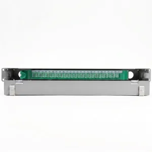
JODF-U1 Optical Patch Panel
Fiber optic patch panel, 12–144 ports, standard design. 19-inch rack mount, cold rolled steel. FC/SC/LC adapters. Factory direct, OEM/ODM, MOQ from 1.
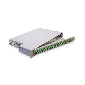
JODF-U2 Optical Patch Panel
Fiber optic patch panel, 12–64 ports, rotary type. 19-inch rack mount, cold rolled steel. FC/SC/LC adapters. Factory direct, OEM/ODM, MOQ from 1.
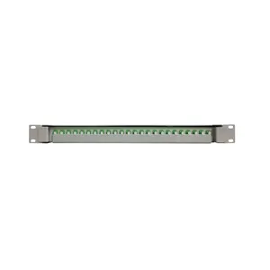
JODF-U3A Optical Patch Panel
Fiber optic patch panel, 24–96 ports, sliding type. 19-inch rack mount, cold rolled steel. FC/SC/LC adapters. Factory direct, OEM/ODM, MOQ from 1.
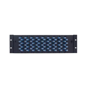
JODF-U3B Optical Patch Panel
Sliding fiber optic patch panel with fiber management options. 19-inch rack, cold rolled steel. FC/SC/LC adapters. Factory direct, OEM/ODM, MOQ from 1.
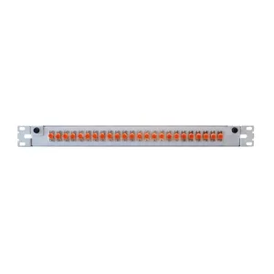
JODF-U4 Optical Patch Panel
24-port flip-cover fiber optic patch panel. 19-inch rack mount, cold rolled steel. FC/SC/LC adapters. Factory direct, OEM/ODM, MOQ from 1.
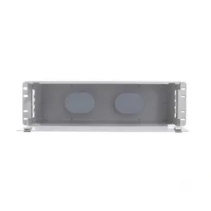
JODF-U5 Optical Patch Panel
Fiber optic patch panel with two radius limiters for fiber management. 19-inch rack, cold rolled steel. Factory direct, OEM/ODM, MOQ from 1.
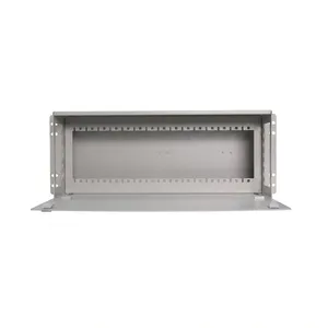
JODF-U6 Optical Patch Panel
4U fiber optic patch panel for PLC splitter accommodation. 19-inch rack, cold rolled steel. FC/SC/LC adapters. Factory direct, OEM/ODM, MOQ from 1.
Stop Calling Everything an ODF — Here Is Where the Patch Panel Belongs
Patch Panel vs ODF — Rack-Mount Unit vs Floor-Standing Frame
The terms "patch panel" and "ODF" get used interchangeably in a lot of product listings. They are not interchangeable. The difference is structural, and it determines where each product goes in your network.
A fiber patch panel is a rack-mount unit. It installs into a standard 19-inch equipment rack using cage nuts and M6 screws. It shares rack space with active equipment — switches, routers, servers. It is typically 1U to 6U tall. You buy a patch panel when you already have a rack and need to add fiber termination capacity inside it.
An ODF (Optical Distribution Frame) is a floor-standing cabinet. It is a standalone piece of furniture — 42U tall, with its own base and cable entry. It does not go into a rack; it stands next to racks. You buy an ODF when you need a dedicated fiber distribution point that does not compete with active equipment for rack space.
| Condition | Use This |
|---|---|
| You have a 19-inch rack with available U-space | Patch panel (JODF-U series) |
| You need a standalone fiber node in the equipment room | ODF (JODF-A/B/C series) |
| You are adding fiber capacity to an existing rack | Patch panel |
| You are building a new fiber distribution point from scratch | ODF |
| You need 1000+ ports in one location | ODF (up to 1440 ports per frame) |
| You need 12–144 ports distributed across multiple racks | Patch panel (one per rack) |
The patch panel's role in the signal path:
In a typical equipment room, the ODF sits near the cable entry point and handles the bulk fiber termination from outside. Patch panels sit inside the racks near the switches and handle the last-meter fiber-to-port mapping. The patch panel is where the technician plugs and unplugs patch cords to reroute connections — it is the workhorse of daily fiber management.
In a Crowded Rack, the Wrong Access Design Turns a 10-Minute Job Into a 40-Minute One
Five Access Mechanisms — Why the Way the Tray Opens Matters
Jergeo offers five distinct access mechanisms across the patch panel line. This is not product variety for its own sake — each mechanism solves a specific physical constraint that technicians face in real equipment rooms.
1. Standard Fixed Tray (JODF-U1)
The trays are fixed inside the housing. You open the front door and access the adapters and splice trays directly. No moving parts to fail, no slides to jam. The trade-off: reaching the rear splice area requires working through the front opening with limited visibility. Best for installations where the panel will be configured once and rarely re-spliced.
The U1 compensates for its fixed design with independent wiring channels — each module's fiber route is physically separated from its neighbors. Pulling a fiber on module 3 does not disturb the routes on modules 2 and 4. In a 144-port panel with 12 modules, this channel isolation is what makes the fixed design viable for high-density deployments.
2. Rotary / Swing-Out (JODF-U2)
The entire tray assembly pivots on a hinge at one side. You swing the tray out like a door, which exposes both the front adapter face and the rear splice area simultaneously. Specifically useful when you need frequent access to splices — the technician can see and reach both sides of the connection.
The trade-off: swing-out requires clearance on one side of the panel. If the rack is tightly packed, the tray may not have room to swing fully. The U2's maximum capacity is 64 ports (vs. 144 for the U1) because the swing mechanism limits module stacking.
3. Sliding Drawer (JODF-U3 / JODF-U4)
The tray slides out on rails, like a drawer. This gives direct front access to the splice and adapter areas without requiring side clearance. The drawer extends far enough to expose all work areas while maintaining fiber bend radius through the slide mechanism.
The U4 variant adds an optional embedded fiber management rack — a separate structure that attaches to the panel housing for routing and storing excess fiber length. This is relevant when your patch cords have significant excess length that needs organized storage rather than being stuffed behind the panel. The U4 ships in two configurations: with or without the fiber management rack.
4. Flip-Cover (JODF-U Type4)
The simplest mechanism: a hinged top cover that flips open to reveal the tray below. No slides, no hinges, no swing-out — just lift the lid and work. The trade-off is capacity: the Type4 is limited to 24 ports in a 1U height. It is also slightly narrower (430mm vs. the standard 482mm) and shallower (230mm), making it the most compact panel in the line. Best for small fiber counts in tight rack spaces.
5. Radius Limiter with Fiber Spools (JODF-U Type5)
This panel is built around two large fiber management spools (radius limiters) rather than splice trays. The spools store and route excess fiber while maintaining the minimum bend radius. Used when the primary requirement is fiber organization and patch cord routing rather than high-density splicing. The Type5 uses M6 cage nuts for rack mounting and ships with the spools pre-installed.
| Your Priority | Choose This | Reason |
|---|---|---|
| Highest port density, set-and-forget | JODF-U1 | 144 ports in 6U, channel isolation |
| Frequent splice access | JODF-U2 | Swing-out exposes both sides |
| Rack with no side clearance | JODF-U3 or U4 | Drawer slide needs front space only |
| Small fiber count, tight space | JODF-U Type4 | 24 ports in a compact 1U |
| Excess fiber storage and routing | JODF-U Type5 | Built-in spools manage slack |
| PLC splitter deployment | JODF-U Type6 | Purpose-built for splitter housing |
Every U You Spend on a Patch Panel Is a U You Cannot Use for a Switch
U-Height vs Port Density — Rack Space Is Not Free
A standard 19-inch equipment rack has 42U of vertical space. After accounting for switches, servers, UPS units, cable managers, and blanking panels, you may have 10–20U available for fiber infrastructure. How you allocate those units determines whether your fiber plant can scale.
| Model | U-Height | Ports | Ports per U |
|---|---|---|---|
| JODF-U1 | 1U | 12–24 | 12–24 |
| JODF-U1 | 2U | 24–48 | 12–24 |
| JODF-U1 | 6U | 96–144 | 16–24 |
| JODF-U2 | 1U / 1.5U | 12–64 | 12–48 |
| JODF-U3 | 1U | 24–48 | 24–48 |
| JODF-U3 | 3U | 96 | 32 |
| JODF-U Type4 | 1U | 24 | 24 |
| JODF-U Type6 | 4U | Up to 120 (splitter) | Up to 30 |
Planning example: 200 fiber ports in a 42U rack
After switches (2U), UPS (2U), cable manager (1U), and 10U reserved for future servers, you have ~27U available.
- Option A: 2× JODF-U1 6U (288 ports) = 12U — too much capacity, wastes 88 ports
- Option B: 1× JODF-U1 6U + 1× JODF-U1 3U (240 ports) = 9U — better fit, leaves 18U for growth
- Option C: 2× JODF-U3 3U (192 ports) = 6U — tight, may need expansion later
Watch the depth
Patch panels range from 230mm (Type4) to 350mm (U3) deep. Check the rack's usable depth before ordering. If the rack has cable management arms or PDUs at the rear, the effective depth available may be 200–300mm less than the rack's nominal depth. A JODF-U3 at 350mm may not fit in a shallow wall-mount rack.
High-Density MPO Connectivity for GPU Clusters
Purpose-built for AI and HPC data centers where every rack unit counts
AI training clusters using NVIDIA H100/B200 GPUs require massive fiber interconnect bandwidth — a single DGX SuperPOD can need over 30,000 fiber connections. Traditional patch panels with individual LC adapters cannot keep up with this density. The AI Fiber Patch Panel uses MPO/MTP multi-fiber connectors to deliver up to 576 fibers in just 4U of rack space, supporting 400G and 800G transceiver architectures with ultra-low insertion loss (≤0.35dB).
Jergeo's AI patch panels are available in 1U (144 fibers), 2U (288 fibers), and 4U (576 fibers) configurations. All models support pre-terminated MPO/MTP cassettes or field-terminable options, with Type A/B/C polarity configurations. OEM/ODM customization available, MOQ from 1 unit.
What 400G and 800G Transceiver Architectures Demand from Your Patch Panel
QSFP-DD and OSFP transceivers use MPO/MTP connectors with 12, 16, or 24 fibers in a single ferrule. A 400G-SR4 uses 8 fibers (4 transmit + 4 receive) on an MPO12. An 800G-DR8 uses 16 fibers on an MPO16. Your patch panel must support these multi-fiber connectors with precision alignment sleeves.
Polarity management becomes critical at these speeds. Type A (straight), Type B (flip), and Type C (pair swap) polarity schemes must be maintained end-to-end. A single polarity mismatch at 400G will drop the entire link. Our AI patch panels use keyed MPO adapters with clear polarity labeling to eliminate miswiring.
Insertion loss budget at 400G/800G is extremely tight. The channel budget for 400G-SR4 is typically 1.5-2.0dB. Each MPO connection in the patch panel must contribute ≤0.35dB. We test every adapter pair and provide test reports with serial-traceable results.
Choosing the Right Form Factor: 1U vs 2U vs 4U
| Form Factor | Max Fibers | MPO Cassettes | Best For |
|---|---|---|---|
| 1U (44mm) | 144 | 12 | Top-of-Rack, leaf switch uplinks |
| 2U (88mm) | 288 | 24 | Spine layer, aggregation cross-connect |
| 4U (176mm) | 576 | 48 | MDA, hyperscale main distribution |
OEM/ODM customization: Every AI data center has unique requirements. The AI fiber patch panel series supports customization of port count, connector type (MPO/MTP 12/16/24-fiber, LC duplex), fiber type (OS2 single-mode, OM3/OM4/OM5 multimode), cable entry direction (top/bottom/rear), polarity scheme (Type A/B/C), rack depth, and material thickness. MOQ starts from 1 unit — we build prototypes for validation before bulk production.
Lead time: Standard configurations ship within 15–20 days. Custom configurations require 25–35 days depending on complexity. All panels are factory-tested for insertion loss, return loss, and polarity before shipment. Test reports are provided with every order.
Related Solutions
See patch panel applications in data center fiber management
Explore Data Center Solution