Splice Distribution Module (SDM)
The building block inside every FDC, ODF, and patch panel — one module handles splicing, fiber storage, and adapter termination in 25mm of vertical space.
A splice & distribution module (SDM) — also called an integrated splice-and-distribution tray — is the atomic unit of fiber management inside optical distribution equipment. Each module is a self-contained cassette that does three things: (1) fuses incoming fibers to pigtails via splice sleeves, (2) stores the fiber slack within a minimum bend radius, and (3) terminates the pigtails on adapter ports at the front face. One module, three functions, zero wasted space.
Jergeo manufactures SDMs in two capacities (12-port and 24-port) and three physical platforms. The A-series (JSDM-A1/A2/B) is the standard 300×180×25mm module found in FDCs and ODFs. The C-series (JSDM-C1/C2/C3) uses a slightly taller 300×182×26mm form factor that allows 24-port density. The compact D/E/F series shrinks the width for tight enclosures — down to 150mm for the JSDM-E mini type. All modules accept FC, SC, and LC adapters (model-dependent) with PC, UPC, or APC polish.
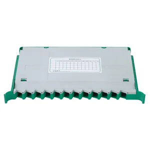
JSDM-A1 Splice & Distribution Module
12-port splice distribution module with middle layer. FC/SC/LC adapters, PC/UPC/APC polish. For ODF, FDC, and patch panels. Direct manufacturer, MOQ from 1.
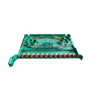
JSDM-A2 Splice & Distribution Module
12-port splice distribution module without middle layer. FC/SC/LC adapters, PC/UPC/APC polish. For ODF and FDC. Direct manufacturer, MOQ from 1.
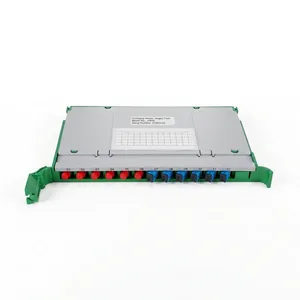
JSDM-C1 Splice & Distribution Module
12-port splice distribution module variant. FC/SC/LC adapters, PC/UPC/APC polish. For ODF and patch panels. Direct manufacturer, MOQ from 1.
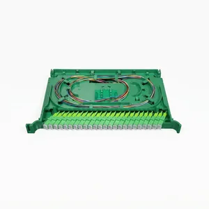
JSDM-C2 Splice & Distribution Module
24-port splice distribution module for high-density fiber management. FC/SC/LC adapters, PC/UPC/APC polish. Direct manufacturer, MOQ from 1.
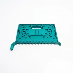
JSDM-C3 Splice & Distribution Module
24-port splice distribution module variant. FC/SC/LC adapters, PC/UPC/APC polish. For ODF and FDC. Direct manufacturer, MOQ from 1.
Three Functions, One Module, 25 Millimeters of Height
What an SDM Actually Does — And Why "Integrated" Matters
Before the integrated splice-and-distribution module existed, every FDC and ODF needed three separate components: a splice tray for fusion splices, a fiber storage reel for slack management, and an adapter panel for port termination. Each component sat on its own shelf. Each required its own cable routing between shelves. And every time a technician needed to add a fiber, they had to work across all three — pulling slack from the storage reel, routing it through the splice tray, and then threading the pigtail down to the adapter panel below.
Back section (splice zone): Incoming fibers from the feeder cable enter through the rear of the module. Each fiber is fusion-spliced to a pigtail. The splice sleeves sit in a dedicated tray that holds up to 12 sleeves for the 12-port model.
Middle layer (storage zone, A1 only): The A1 includes a middle layer — a flat plate between the splice zone and the adapter zone. This plate serves as fiber slack storage. After splicing, the excess pigtail length is coiled on this plate with a minimum bend radius of 30mm (per ITU-T G.652D fiber specification). This keeps the fiber organized and accessible when the module is pulled out for maintenance.
Front section (adapter zone): The pigtails terminate on adapter ports at the front face of the module. This is where patch cords plug in to route signals to the next node.
Why the "no middle layer" option (JSDM-A2) exists: Some installations — particularly in ODFs where fiber routing runs vertically through cable management channels — do not need internal slack storage within the module. The fiber slack is managed by the ODF's central routing system. Removing the middle layer simplifies the module and reduces the risk of fiber tangles during high-density installations.
| Enclosure | SDM Count | SDM Capacity | Total Ports |
|---|---|---|---|
| JFDC-1152A | 96 × JSDM-A1 | 12 ports each | 1152 |
| JFDC-576A | 48 × JSDM-A1 | 12 ports each | 576 |
| JFDC-288A | 24 × JSDM-A1 | 12 ports each | 288 |
| JFDC-144A | 12 × JSDM-A1 | 12 ports each | 144 |
| JFDC-72A | 6 × JSDM-A1 | 12 ports each | 72 |
How SDMs scale inside FDCs
A JFDC-1152A contains 96 SDMs. A JFDC-576A contains 48 SDMs. The SDM is the replaceable unit — if a module is damaged, you pull it out and insert a replacement without touching adjacent modules. This is the core advantage of modular fiber management: you never have to take down an entire cabinet to fix one bad splice. With 24-port C-series modules, the same FDC body doubles its capacity — a 576-port cabinet becomes 1152 ports without changing the enclosure dimensions.
Pick the Wrong Module Series and You Cannot Fit Your Cabinets — Or You Waste Half the Space
Three Platforms, Three Use Cases — A-Series, C-Series, and Compact
A-Series (JSDM-A1, A2, B) — The Workhorse: 300×180×25mm, 12 ports. This is the module that ships inside Jergeo FDCs. The 180mm width is the standard rail spacing in FDC and ODF tray frames. JSDM-A1 is the full-featured version with the middle storage layer. JSDM-A2 removes the middle layer for ODFs. JSDM-B is adapter-restricted to SC only — for FTTx networks that use only SC/APC throughout (common in GPON deployments).
C-Series (JSDM-C1, C2, C3) — The Density Play: 300×182×26mm (2mm wider, 1mm taller), 12 or 24 ports. That tiny dimensional increase is enough to double the port count in the C2 and C3 models. JSDM-C2 (24-port, SC/LC only) and JSDM-C3 (24-port, FC/SC/LC) are for high-density applications — data center ODFs, large FDCs where port count per rack unit is the primary constraint.
Compact Series (JSDM-D, E, F) — For Small Enclosures: JSDM-F is 320×200×25mm (wider, for larger ODFs). JSDM-D is 200×180×25mm (narrower, for FDBs). JSDM-E is 150×180×25mm (the mini type, for the tightest enclosures — optical terminal boxes with 2–4 adapter ports).
| Enclosure | Available Width | Recommended SDM | Why |
|---|---|---|---|
| FDC (72–1152 ports) | 180mm rail spacing | JSDM-A1/A2 | Standard FDC tray width |
| ODF with center routing | 180mm rail spacing | JSDM-A2 | No middle layer — ODF has its own fiber management |
| ODF high-density | 182mm rail spacing | JSDM-C2/C3 | 24 ports per module maximizes rack port density |
| FDB / small terminal box | 150–200mm | JSDM-D or JSDM-E | Width constraint rules out A/C series |
| Patch panel (19-inch rack) | Varies by panel design | JSDM-A1 or JSDM-F | Check panel shelf width before ordering |
Get This Wrong and You Cannot Meet Your Link Budget — Period
PC vs UPC vs APC — The Polish Type Controls Your Return Loss Budget
Every fiber adapter has a ferrule — the ceramic tip where two fiber end faces meet. How that ferrule tip is polished determines how much light reflects back toward the laser source at each connection point. The SDM is where you specify the polish type, because the adapter ports on the module faceplate are the connection points.
PC (Physical Contact): Slightly convex dome polish. Return loss ≥40 dB. Color code: Blue ferrule. Application: Legacy telecom, low-speed links, multimode networks. PC is rarely specified for new single-mode builds.
UPC (Ultra Physical Contact): Finer convex dome polish with tighter curvature. Return loss ≥50 dB. Color code: Blue connector body. Application: The workhorse for data centers, enterprise networks, and telecom backbones. The 10 dB return loss improvement over PC is the difference between a link that passes BER testing and one that does not at 10 Gbps and above.
APC (Angled Physical Contact): 8° angled polish — reflected light is deflected into the cladding. Return loss ≥60 dB. Color code: Green connector body. Application: CATV / video overlay, FTTx PON networks (GPON, XGS-PON). APC is mandatory whenever the fiber carries analog video or when the laser source is sensitive to back reflection.
| Scenario | Recommended Polish | Why |
|---|---|---|
| GPON / XGS-PON (with RF video overlay) | APC | Back reflection from video overlay laser must be suppressed below -60 dB |
| GPON (data only, no video) | UPC or APC | UPC meets -50 dB return loss; APC is safer for future video upgrade |
| Point-to-point fiber (enterprise) | UPC | No splitter, no analog signal — UPC is sufficient and cheaper |
| Legacy multimode network | PC | Existing infrastructure uses PC; no benefit to upgrading until fiber is replaced |
The One Rule You Cannot Break
Never connect APC to PC or UPC. An APC ferrule (8° angle) mated with a flat or convex ferrule creates an air gap that causes massive insertion loss (1–2 dB) and return loss degradation. In a PON network, this can take down every subscriber on that split. The green connectors exist specifically so technicians can identify APC at a glance and avoid cross-mating.