Fiber Optic Splitter — PLC Cassette
Where the PON signal splits — a planar lightwave circuit inside a plug-in cassette, and the slots that hold them.
A PLC splitter cassette is the packaging format that makes a planar lightwave circuit (PLC) splitter usable inside an FDC, ODF, or fiber distribution box. The bare PLC chip itself — a silica waveguide on a silicon substrate — is fragile and impractical to handle in the field. The cassette encloses the chip, routes the input and output fibers, terminates them on adapter ports at the front face, and protects everything in a rigid plastic or metal shell that slides into a standard tray rail or card slot.
Jergeo manufactures three types of PLC splitter products: (1) tray-type cassettes that slide into the same 180mm-wide rails as splice-and-distribution modules, available in 1x16 and 1x32 split ratios; (2) card-type cassettes — smaller, vertically-oriented modules designed for dedicated splitter slots, available in 1x8 split ratio; and (3) splitter slots — the mounting frames that hold card-type and box-type PLC splitter modules inside FDCs and FDBs. All products use single-mode fiber, operate from -40 to +85 C, and support FC, SC, and LC adapters (model-dependent) with PC, UPC, or APC polish.
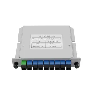
JPLCC-8A Card Type PLC Splitter
1x8 card type fiber optic splitter module for FTTH PON. FC/SC/LC adapters, single-mode, -40 to +85°C. Direct manufacturer, MOQ from 1.
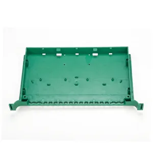
JPLCT-16A Tray Type PLC Splitter Chassis
1x16 tray type fiber optic splitter module for FTTH PON. FC/SC/LC adapters, single-mode, -40 to +85°C. Direct manufacturer, MOQ from 1.
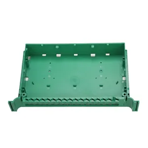
JPLCT-32A Tray Type PLC Splitter Chassis
1x32 tray type fiber optic splitter module for FTTH PON. FC/SC/LC adapters, single-mode, -40 to +85°C. Direct manufacturer, MOQ from 1.
One Input, N Outputs — The Split That Makes FTTH Economically Possible
What a PLC Splitter Cassette Actually Does in a PON Network
A PON (Passive Optical Network) shares a single fiber from the OLT (Optical Line Terminal) in the central office among 16, 32, 64, or 128 subscribers. The device that divides that optical signal is the PLC splitter. It takes one input fiber and splits it evenly — every output port receives the same optical power (within the uniformity specification).
In a GPON network with a 1x32 split, the OLT transmits at +3 dBm downstream. After the splitter, each subscriber receives approximately 3 minus 15.0 equals -12 dBm (theoretical split loss for 1x32 is 10 times log10 of 32 = 15.0 dB), plus the actual insertion loss of the PLC chip (typically 0.5 to 1.0 dB above theoretical), plus fiber and connector losses. The ONT (Optical Network Terminal) at the subscriber premises needs at least -27 dBm to maintain a BER better than 10 to the minus 3 per ITU-T G.984.2. That leaves a link budget of about 14 dB for fiber runs and connector losses. The splitter insertion loss — not just the theoretical split ratio, but the real insertion loss including uniformity and PDL — determines whether your network makes budget or does not.
Why cassette format matters: The PLC chip inside the cassette is the same whether you buy a bare-fiber splitter, a steel-tube module, or a cassette. The difference is how the chip is packaged and how it connects to your network. A cassette with pre-terminated adapters means:
- No field splicing of the splitter input/output fibers. The splitter comes from the factory with connectors already installed and tested.
- Hot-pluggable into an FDC or ODF slot. If a splitter fails, you pull the cassette and insert a replacement — no fiber splicing, no service truck with a fusion splicer.
- Factory-tested insertion loss and uniformity. Each cassette ships with a test report documenting the IL on every port.
Where the cassette sits in the PON signal path:
OLT (Central Office) -- Feeder Fiber -- FDC -- PLC Splitter Cassette (this product) -- Drop Fibers -- ONT (Subscriber)
In a centralized split architecture (common in GPON), the splitter cassette sits inside the FDC. In a cascaded split architecture (common in XGS-PON), there may be a first-stage 1x4 or 1x8 splitter at the FDC, and a second-stage 1x8 splitter closer to the subscriber at the FDB.
The Form Factor Is Not an Aesthetic Choice
It Determines Which Enclosure You Can Install Into
There are two cassette shapes, and they go into different mounting systems inside the same FDC or ODF.
Tray-Type Cassette (JPLCT-16A, JPLCT-32A): Dimensions: 300x180x25mm (1x16) or 310x180x51mm (1x32). Same footprint as a splice-and-distribution module (JSDM-A1). Mounts in the horizontal tray rails of an FDC or ODF.
The tray-type cassette is designed to coexist with splice-and-distribution modules in the same enclosure. In a 576-port FDC, some tray positions hold SDMs (for splicing and adapter termination) and others hold PLC splitter cassettes (for signal splitting). They share the same 180mm rail spacing and the same pull-out mechanism. A technician can identify which tray is a splitter and which is a splice module by looking at the front faceplate — the splitter cassette has 17 adapter ports for 1x16 (1 input + 16 outputs) or 33 ports for 1x32, while the SDM has 12 ports in a single row.
The 1x32 cassette (JPLCT-32A) is 51mm tall — it takes up the vertical space of two 25mm trays. This is because the 32 output fibers require more internal routing space than 16. When planning your FDC layout, count each JPLCT-32A as occupying two tray positions.
Card-Type Cassette (JPLCC-8A): Dimensions: 130x110x25mm. Mounts vertically in a dedicated splitter slot (JCC-A or JCC-B). Does not share the SDM tray rails.
The card-type cassette is a smaller module designed for a different mounting system. Instead of sliding into horizontal tray rails, it plugs vertically into a splitter slot — a dedicated frame that holds multiple card-type cassettes side by side. The JPLCC-8A is the splitter module; the JCC-A/B/C are the slots that hold them.
Why two systems exist: In a 1x32 centralized split deployment, the FDC needs only a few splitter cassettes (one per PON port from the OLT), but each cassette handles 32 subscribers. The tray-type is efficient here — you install a JPLCT-32A in one tray position, and 32 fibers come out. But in a cascaded split or a 1x8 split deployment, you need many small splitters distributed across multiple enclosures. The card-type system lets you pack up to 4x 1x8 splitters into a single JCC-A slot (130x104x108mm) — that is 32 subscribers served from a slot that takes up less space than two tray positions.
| Scenario | Split Ratio | Recommended Cassette | Mounting | Why |
|---|---|---|---|---|
| Centralized GPON, 1x32 | 1x32 | JPLCT-32A | FDC tray rails | One cassette = 32 subscribers, simple layout |
| Centralized GPON, 1x16 | 1x16 | JPLCT-16A | FDC tray rails | Same rail system as SDMs, easy mixed layout |
| Cascaded 1x8 + 1x8 | 1x8 | JPLCC-8A x 2 | JCC-A or JCC-B slot | Two-stage split, high card density per slot |
| Small FDB, 1x8 only | 1x8 | JPLCC-8A | JCC-A slot inside FDB | Compact, fits in small enclosures |
| XGS-PON, 1x32 | 1x32 | JPLCT-32A | FDC tray rails | Same as GPON, higher split count |
Theoretical Split Loss Is Just the Starting Point
You Need to Budget for the Real Insertion Loss
A PLC splitter does not just lose the theoretical minimum. The real insertion loss includes the split loss (physics), the excess loss (imperfections in the waveguide), and the connector loss (at the adapter interfaces). Here are the numbers you need for link budget calculations.
| Split Ratio | Theoretical Split Loss | Typical IL (P grade) | Max IL (S grade) | Uniformity (Max) |
|---|---|---|---|---|
| 1x2 | 3.0 dB | 3.6 dB or less | 4.0 dB or less | 0.8 dB |
| 1x4 | 6.0 dB | 7.0 dB or less | 7.4 dB or less | 0.8 dB |
| 1x8 | 9.0 dB | 10.3 dB or less | 10.5 dB or less | 0.8 dB |
| 1x16 | 12.0 dB | 13.5 dB or less | 13.7 dB or less | 1.2 dB |
| 1x32 | 15.0 dB | 16.5 dB or less | 17.0 dB or less | 1.5 dB |
| 1x64 | 18.0 dB | 20.0 dB or less | 20.5 dB or less | 2.0 dB |
Source: Typical values compiled from Telcordia GR-1209-CORE and ITU-T G.671 specifications. P grade = premium; S grade = standard.
What these numbers mean for your link budget:
Take a GPON link with 1x32 split: OLT transmits at +3 dBm, splitter IL is 17.0 dB (S grade max), fiber loss is 0.35 dB/km at 1310nm (G.652D), and you have 2 connector pairs at 0.3 dB each. For a 10 km fiber run:
Received power = +3 - 17.0 - (0.35 x 10) - (0.3 x 2) = +3 - 17.0 - 3.5 - 0.6 = -18.1 dBm
ONT sensitivity is typically -27 dBm (GPON class B+). Margin = -18.1 - (-27) = 8.9 dB. That is a healthy margin. But if you use a cascaded 1x4 + 1x8 split instead of a single 1x32, the total split loss goes up (6.0 + 10.5 = 16.5 dB for the split, plus the extra connector pair between the two splitters = +0.3 dB), and you have one more splice point and fiber segment. The margin drops to about 5.1 dB — still positive, but tighter. This is why centralized split (single 1x32) is preferred for GPON: fewer components in the path, lower total insertion loss, simpler maintenance.
Uniformity — why it matters more than you think:
The uniformity spec (0.8 dB for 1x8, 1.5 dB for 1x32) means the difference between the best and worst output ports on the same splitter. In a 1x32 cassette, one subscriber may receive -16.0 dBm from the splitter while another receives -17.5 dBm. That 1.5 dB difference is the uniformity. If your link budget is tight, the subscriber on the worst port may not meet the ONT sensitivity requirement. Always budget for the worst-port insertion loss (max IL + uniformity), not the typical value.