Fiber Optic Patch Panel Buyer's Guide
By Jergeo Engineering Team | Updated June 2026 · 10 min read

A fiber optic patch panel terminates incoming fiber cables and provides accessible adapter ports for cross-connecting to active equipment. It sits in a standard 19-inch equipment rack, protects splice points, and gives technicians a structured point to test, reroute, or troubleshoot fiber links.
Summary
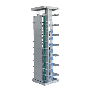
A fiber patch panel (ODF) terminates fiber cables and provides cross-connect access in server rooms, available in wall-mount, rack-mount, and floor-standing configurations from 12 to 576 ports.
Choosing the wrong panel — too few ports, the wrong connector type, or insufficient cable management space — creates problems that are expensive to fix after deployment. This guide walks through the specifications that matter and shows how Jergeo's JODF series covers common configurations.
What is a fiber optic patch panel
A fiber optic patch panel is a rack-mount enclosure that houses fiber splice trays, adapter plates, and cable management components. It serves three functions:
- Termination: incoming trunk or distribution cables are stripped, and individual fibers are spliced to pigtails that connect to adapters on the front panel
- Cross-connect: patch cords connect the front-panel adapters to switches, OLTs, or other active equipment
- Protection: the enclosure shields splice points from physical damage, dust, and bending beyond the fiber's minimum bend radius
Patch panels are used in data centers, telecom central offices, FTTH distribution points, enterprise wiring closets, and CATV headends. They are passive devices — no power, no electronics — which means they need to last decades without replacement. Build quality matters.
Key specifications to consider
Before selecting a specific model, evaluate these parameters against your deployment requirements.
Port count
Port count is the first number buyers look at. A "24 port fiber patch panel" means 24 adapter positions on the front face. For duplex adapters (which most single-fiber connections use), each position carries one fiber link. Port counts range from 12 to 144 in a single 1U panel, depending on adapter type and density design.
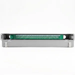
The Jergeo JODF-U1 series supports 12 to 144 ports across 1U to 6U sizes. The 1U configuration starts at 12 ports with 1 module; a full 6U chassis can hold 12 modules for up to 144 ports. If you need 12 port fiber patch panel capacity, the 1U JODF-U1 is the minimum form factor. For a 24 port fiber patch panel configuration, the same chassis with 2 modules covers it.
Connector type and adapter compatibility
The adapter type determines which patch cords you'll use. Common adapter types include:
- LC: small form factor (1.25mm ferrule), the most common in data centers and high-density deployments. An LC fiber patch panel gives you the highest port density per rack unit
- SC: push-pull connector with 2.5mm ferrule, common in FTTH and telecom central offices
- FC: threaded connector, used in test equipment and some legacy installations
All Jergeo JODF-series panels (U1 through U6) support FC, SC, and LC adapters. The adapter plates are modular — you can mix connector types within the same panel if needed, which is useful during migration from one connector standard to another.
Adapter style: simplex vs duplex
Adapters come in simplex (single fiber) and duplex (two fibers in one housing) configurations. Most data center deployments use duplex LC adapters because each link requires a TX and RX fiber. FTTH networks sometimes use simplex SC adapters since each ONT connection is a single fiber with WDM. Specify the adapter style when ordering — the panel's module slots are sized accordingly.
Rack compatibility
All JODF-series panels use standard 19-inch rack mounting. The width is 482mm (or 485mm for the JODF-U3A sliding model). Panel heights range from 1U (43mm) to 6U (242mm). Make sure your rack has enough vertical space and that you account for cable management bars above or below the panel if required by your installation standard.
Jergeo JODF series at a glance
The table below summarizes the seven models in the JODF series and their core specifications.
| Model | Design | Port Range | Size (H×W×D) | Key Feature |
|---|---|---|---|---|
| JODF-U1 | Standard | 12–144 | 1U–6U, 482mm wide | Widest capacity range |
| JODF-U2 | Rotary | 12–64 | 1U, 482mm wide | Rotary access in tight spaces |
| JODF-U3A | Sliding | 24–96 | 1U–3U, 485mm wide | Slide-out for rear access |
| JODF-U3B | Sliding | Various | 1U–3U, 482mm wide | Sliding + cable management |
| JODF-U4 | Flip-cover | 24 | 1U, 430mm wide | Compact, simple structure |
| JODF-U5 | Standard | Various | 3U, 482mm wide | Dual radius limiters |
| JODF-U6 | Standard | Various | 4U, 482mm wide | PLC splitter accommodation |
LC vs MPO adapter panels
The choice between LC and MPO adapters affects your panel specification directly.
LC duplex panels are the standard for 1G/10G/25G links. A 1U LC panel typically holds 24 duplex ports (48 fibers). High-density variants use offset adapters or sliding trays to fit more ports in the same space. LC connectors use a 1.25mm ferrule, and the small size is what enables high density. If your deployment is primarily 10G Ethernet or below, an LC fiber patch panel is the default choice.
MPO panels carry 12, 16, or 24 fibers per connector. They are used with parallel optics transceivers (40G, 100G, 400G). A single MPO adapter replaces 6 to 12 LC duplex positions. MPO panels are essential for backbone cabling in structured data center environments running 40G+, but they require specialized inspection tools and polarity management discipline.
For mixed environments — which is most real-world deployments — modular panels that accept both LC and MPO adapter strips in the same chassis give you flexibility. Jergeo's modular adapter strip design supports this approach across the JODF-U1 and JODF-U3 series.
Standard vs high-density panels
Panel density is determined by how many adapter ports fit in a given rack unit height. Here's how the categories break down:
- Standard density: 12–24 LC duplex ports per 1U. Adequate for most enterprise wiring closets and small central office deployments
- Medium density: 24–48 LC duplex ports per 1U. The JODF-U3A sliding panel at 96 ports in 3U achieves 32 ports/U
- High density: 72+ LC duplex ports per 1U. Achieved through offset adapter arrangements, smaller adapter housings, or specialized cassette designs
A high density fiber patch panel saves rack space but costs more per unit and can make cable management more challenging — more patch cords in a smaller area means tighter bend radius risk. Choose high density when rack space is the primary constraint. Choose standard density when ease of maintenance and cable routing matter more.
The Jergeo JODF-U1 in its 6U configuration holds up to 144 ports (12 modules × 12 ports each), which works out to 24 ports per rack unit at maximum capacity. For deployments that need more than 24 ports per U, a dedicated high-density cassette panel from another product line would be needed — but for most ODN (Optical Distribution Network) deployments, the JODF-U1's modular capacity is sufficient.
How to calculate port requirements
Start with the total fiber count of all cables that will terminate on the panel, then add spare capacity. The calculation:
Total ports needed = (Fiber count per cable × Number of cables) + Spare capacity
Spare capacity is typically 10–20% of the base count. For a 48-fiber trunk with 20% spare, you need 58 ports — round up to the next available panel configuration (e.g., 72 ports with a 3U JODF-U3A).
Example calculation for an FTTH distribution point:
- 2 incoming 48-fiber cables = 96 fibers
- 15% spare = 14 additional ports
- Total = 110 ports
- Select: JODF-U1 in 5U or 6U configuration (up to 144 ports) — the 6U gives room for future expansion
Example for a data center top-of-rack deployment:
- 24 servers × 2 fibers each (duplex LC) = 48 ports
- 10% spare = 5 ports
- Total = 53 ports → a 2U JODF-U3B panel or a pair of 1U JODF-U1 panels works
Physical specifications that matter
Beyond port count, these specs determine whether the panel will perform reliably in your environment:
| Parameter | Value (JODF series) | Why it matters |
|---|---|---|
| Material | Cold rolled steel | Structural rigidity, EMI shielding, longevity |
| Working temp | -5 to +40°C | Standard indoor range; sufficient for climate-controlled rooms |
| Insulation resistance | >1000MΩ at 500VDC | Ensures no signal leakage between adjacent fibers under voltage stress |
| Proof voltage | 3000VDC / 1 min | Dielectric safety margin for shared conduit scenarios |
| Endurance life | >1000 mating cycles | Adapter insertions before wear — sufficient for routine maintenance access |
| Protection class | IP20 | Indoor use; protects against finger-sized objects, no water/dust ingress rating |
Panel design types explained
The mechanical design of the panel affects how technicians access fiber during installation and maintenance:
- Standard fixed (JODF-U1, U5, U6): the simplest design. Front door opens to expose adapters and splice trays. Low cost, high reliability. The U6 adds dedicated space for PLC splitters (supports 1×8 up to 15 units, 1×16 up to 7 units, or 1×32 up to 3 units)
- Rotary (JODF-U2): the adapter plate rotates forward, exposing the splice area behind it. Useful when rack depth is limited and technicians need to access splices without removing the panel from the rack
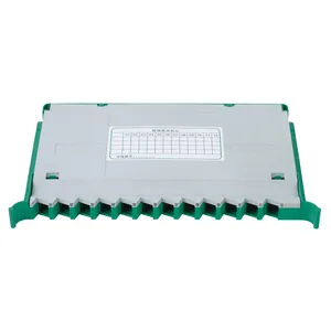
- Sliding (JODF-U3A, U3B): the entire tray slides out on rails, like a drawer. This provides full access to rear cable entry and splice trays without disturbing front patch cords. The JODF-U3A supports 24–96 ports in 1U–3U; the U3B adds integrated cable management with M6 bayonet mounting
- Flip-cover (JODF-U4): a hinged cover lifts to expose adapters. Compact form factor (45×430×230mm) makes it suitable for wall-mount or compact rack installations where 24 ports are sufficient
Indoor deployment considerations
All JODF-series panels are rated for indoor use (IP20, -5 to +40°C operating range). When planning indoor deployment, consider the following:
Cable entry and bend radius
Fiber cables enter through the rear or bottom of the panel. The minimum bend radius for single-mode fiber is typically 30mm during installation and 15mm after. Panels with integrated radius limiters (like the JODF-U5 with its dual radius limiters) prevent technicians from accidentally bending fibers beyond spec during patching. Always route cables through the designated wiring channels — the independent wiring channels on the JODF-U1 are designed specifically for this.
Rack airflow and panel placement
In data centers, patch panels are typically placed at the top or bottom of the rack, separate from active equipment. This prevents patch cords from blocking airflow to servers and switches. In telecom cabinets, panels are stacked with ODFs and distribution frames — plan the vertical layout before installation to avoid conflicts.
Future expansion
The modular design of the JODF series lets you start with fewer modules and add more as fiber counts grow. A JODF-U1 in 2U configuration with 24 ports can later be expanded to 48 ports by adding modules, as long as the chassis height supports it. If you expect significant growth, specify a larger chassis from the start — the incremental cost of a 3U vs 2U chassis is small compared to the cost of replacing a panel after deployment.
Labeling and documentation
Every adapter port and every fiber in the splice tray should be labeled. Use a consistent numbering scheme that maps to your cable schedule. The front door of each JODF panel is the natural place for a port assignment label. Take photos during installation — they save time during troubleshooting months later.
Related Products
References
- TIA-568 — Telecommunications Industry Association cabling standards for fiber patch panel specifications
- FOA Patch Panel Guide — The Fiber Optic Association reference on patch panel installation and management
Key takeaway
Start with your total fiber count and add 15–20% spare capacity. Choose the adapter type (LC/SC/FC) that matches your active equipment. Pick the mechanical design (fixed/rotary/sliding) based on your rack depth and maintenance access needs. The JODF-U1 offers the widest range (12–144 ports, 1U–6U) for general deployments; the JODF-U3 sliding series is best when rear cable access matters; the JODF-U6 is purpose-built for FTTH deployments that integrate PLC splitters in the same enclosure.
Related products
Related Articles
MPO vs LC Patch Panel
Choosing between MPO and LC adapter configurations for high-density data center patch panels.
Read Article →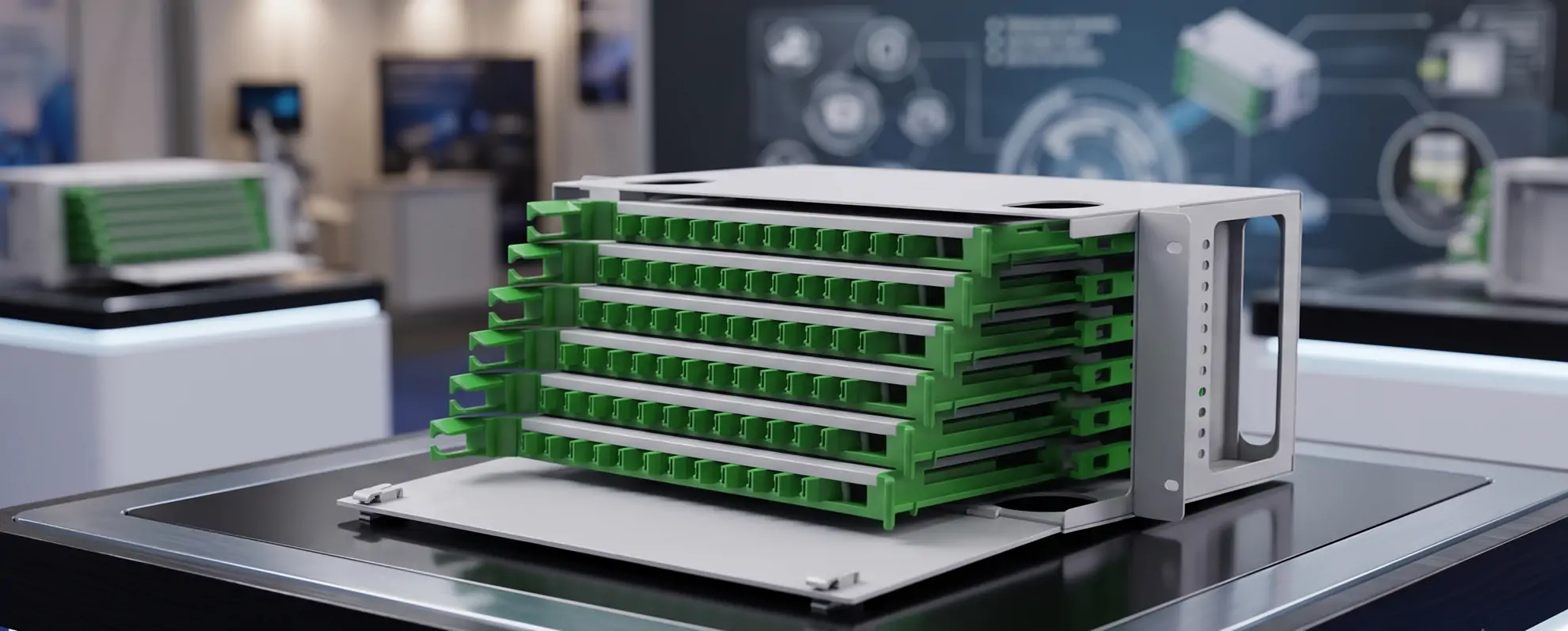
ODF vs Fiber Patch Panel: What's the Difference?
When to use an ODF frame versus a standard patch panel for indoor fiber management.
Read Article →
Fiber Splice Closure Guide
Dome vs inline splice closure selection criteria and how they complement indoor patch panels.
Read Article →