Fiber Optic Terminal Box Installation: A Step-by-Step Field Guide
By Jergeo Engineering Team | Updated September 2026 · 11 min read
The fiber optic terminal box is the last passive device the signal passes through before it becomes a service. In an FTTH drop, the box is where the distribution fiber is terminated and handed off to the subscriber — so the box you install, and the way you install it, directly determine whether that subscriber gets reliable service or intermittent faults that are costly to chase later. We have opened enough misinstalled terminal boxes in the field to list, almost without exception, the same repeated mistakes: fibers terminated at minimum length with no service loop, cable entry eyes sealed against rain but left open to the bottom, fibers forced into radius grooves at bends a hair too tight, and covers closed over fibers that were never secured. Installed correctly, the same box runs for the life of the network without a return visit.
This guide walks the full install from site survey to acceptance test. It covers where the box fits in the ODN, how to choose and prepare the location, wall-mounting step by step, cable entry and sealing, fiber splicing and management, IP rating decisions, and the tests that tell you the job is done. It applies to the Jergeo JOTB terminal box range — from the 2-port mini box up to the 192-port outdoor box — and to any similar field-installed passive termination point.
Summary
Install a fiber optic terminal box in six stages: survey the site and pick a sheltered, accessible location matched to exposure and port count; mount the box level on a solid surface; route and seal cable entry against water; splice or terminate fibers leaving a generous service loop; manage every fiber along the radius paths and close the cover without pinching; then run an acceptance test — power meter on each port and, where required, an OTDR — and record the readings. Most field faults are a dirt spec, a loose connection, or an unsecured loop, not a bad splice.
Why the Terminal Box Is the Most Hands-On Device in the Drop
Every device in the ODN gets touched at installation, but the fiber optic terminal box is the one most likely to get touched again. It sits at the customer boundary, so every fiber handling decision balances against a service that is already sold. A day-one mistake — a tight bend, a fiber under tension, a dirty adapter face — adds a hard loss to that path that no later patch removes. Getting the install right the first time is cheaper than every maintenance visit downstream.
Step 1 — Decide Where the Box Fits in the Network
Place the box in the signal path before you place it on the wall. On the distribution side of a typical FTTH plant, the path runs: OLT at the central office → feeder cable → fiber distribution cabinet (FDC) → distribution cable → fiber distribution box (FDB) or a direct drop → the fiber optic terminal box → ONT at the customer. The terminal box is that drop point: it receives the distribution fiber, terminates it on an adapter, and presents a fixed port for the drop cable.
That role decides two things up front. First, the box belongs at the subscriber boundary — at or near the premise, not fifty meters down the road. Second, because the box terminates fibers carrying live or soon-to-be-live service, the port count and size must match today's fibers with room to grow.
Step 2 — Match the Box to the Site
The most reliable installs start with sizing, not drilling. Walk the site and settle four things before a single hole is made.
- Port count with headroom. A single-family drop often needs 4–8 ports; a small MDU entry usually 12–24; a building entrance or riser handoff can need 48 up to 192. Choose the box that covers today's terminated fibers with room to grow — you can leave ports empty, but you cannot add ports to a full box.
- Exposure and IP rating. Permanent outdoor, facing the weather → IP65 (JOTB-192A, JOTB-48B). Sheltered, under an eave, indoors, or a dry corridor → IP54 is adequate (JOTB-24A, JOTB-12A, JOTB-8A, JOTB-4A). Skipping this is the fastest way to a water-damaged tray.
- A solid mounting surface. Concrete, block, or timber takes expansion bolts cleanly. Hollow cladding needs a backing plate. A box that flexes on the wall passes vibration to the fibers and lets water track in through the back.
- How the cable arrives. Note where the feeder enters relative to the box. The entry should sit below or beside the cable holes so the cable runs in naturally, without a sharp reverse bend.
Assemble the kit: the box, expansion bolts sized for the wall, a level, a drill with masonry bits, a cable stripper, a cleaver, a fusion splicer (or pre-terminated pigtails), alcohol and lint-free wipes, a power meter and light source, and, for routed outdoor drops, an OTDR.
Step 3 — Mount the Box Level on a Solid Surface
Mount the box where the drop cable reaches it without a tensioned pull, and where a technician can later open it and work with both hands. For a single-family premise that usually means 1.2–1.5 m above grade — low enough to work without a ladder, high enough to clear splash. In an MDU or riser, place it at the point where the riser cable terminates and internal drops fan out.
Mark the mounting holes with the box as a template, then drill and set the anchors. Hold the box against the wall and check it is level in both directions before tightening — a box that leans looks wrong on the facade and, more importantly, changes how water sheds across the cover and how the tray sits. Tighten the bolts to seat the gasket evenly; do not overtighten and crush the seal.
Step 4 — Route and Seal Cable Entry
Water at cable entry is the single most common terminal box failure in the field. The entry — a gland, grommet, or knockout — must do two jobs: hold the cable securely so nothing pulls on the fibers inside, and keep water out.
- Size the opening to the cable. A gland made for a larger cable gapes around a thin drop and lets water in. Use the correct grommet or the right entry point for the cable diameter.
- Bring outdoor cable in from below or the side. That way water drips off rather than pooling at the opening. Seal every unused entry with a plug so the box stays dust- and watertight.
- Clamp the jacket, not the fibers. Secure the cable jacket in the strain clamp; the fibers that emerge from stripping are fragile and must never carry pull. Tie the cable off, then let the fibers run free into the tray.
On IP65 outdoor boxes, verify the entry seal after routing by closing the box and checking for gaps. This is the step most often skipped and the one that costs the most later.
Step 5 — Splice, Terminate, and Protect the Fibers
Two scenarios cover most boxes. In a pre-terminated box, you splice the incoming distribution fiber directly to the pigtail already attached to the splitter or adapter. In a field-spliced box, you terminate incoming fibers onto adapter ports directly. Either way, the discipline is the same.
- Strip clean and cleave square. Clean every fiber with alcohol and a lint-free wipe before splicing. One spec of contamination reflects light and reads as a loss spike on an OTDR.
- Splice, then protect. Fusion-splice and slide the splice sleeve over the joint, then seat the sleeve in its holder in the tray. Never bury loose sleeves; they must sit in their designated positions so they cannot snag or shift when the cover closes.
- Leave a service loop. Before locking down, leave at least one full loop of excess in the tray. That slack lets a future technician re-terminate a damaged connector without re-splicing the run.
On boxes with PLC splitter modules, seat the splitter in its bay and connect the input and output ports by hand, keeping the pigtail tails on their radius path.
Step 6 — Manage Every Fiber Along the Radius Paths
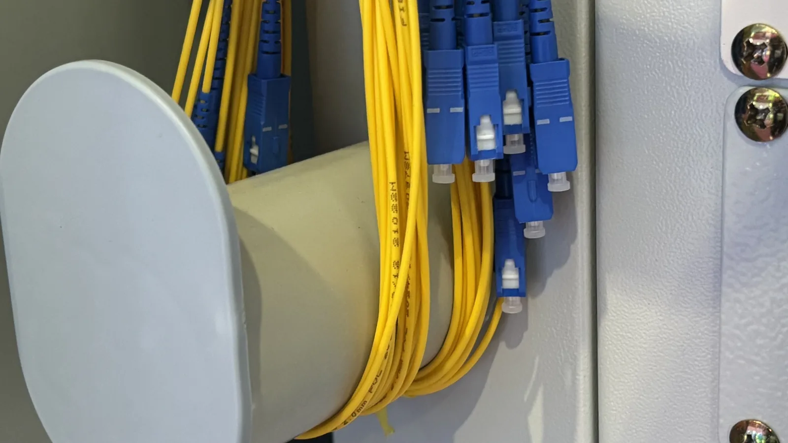
The fiber management inside the box exists for one reason: to keep every bend above the minimum bending radius and every fiber out of the way of the cover and door. This is not cosmetic.
- Use the molded radius guides. Route each fiber along the radius grooves cast into the tray, never across the middle on a shortcut. Standard single-mode pigtails should not bend tighter than about 30 mm; the tray's radius is designed to that limit.
- Secure with the supplied ties. After routing, fasten bundles to the tie points so nothing shifts when the box is closed, opened, or handled. An unsecured fiber that jumps its groove during a door close is a fault waiting to happen.
- Seat splitters and sleeves. Confirm PLC modules and splice sleeves are in their holders before closing — this stops the two most common "mystery" faults: a rattling splitter and a sleeve pressing against the lid.
When the tray is fully routed, close it carefully and confirm no fiber is pinched between the tray and lid or against the hinge.
Step 7 — Close, Seal, and Label
Before the box goes live, close it with a clean gasket and a continuous seal. On IP65 boxes, check nothing prevents the cover from seating flush — a stray fiber, a screw head, or debris on the seal. Then label. A label recording port count, feeder cable ID, date, and installer is what makes a box maintainable at year three instead of a re-survey. Add a clear physical label on the outside and, on larger boxes, a port map inside the cover.
Create-a-Flow: Choosing the Right Terminal Box
Walk this decision path in the field and you will not end up with the wrong-size box on the wall.
- How many subscribers will terminate here? 2–12 → mini box; 24 → standard ABS; 48 → dual-door steel; up to 192 → high-density steel.
- Is the box permanently outdoors in the weather? Yes → IP65. No / sheltered → IP54.
- Does the drop carry a metallic strength member in a lightning-prone area? Yes → metal body and bonded entry. No → dielectric ABS is fine.
- Is the mounting wall solid? Yes → standard anchors. No → add a backing plate.
IP Rating and Material: Match the Box to Exposure
The IP rating you chose at procurement must match where the box ends up. IP54 boxes protect against limited dust and splashing water — right for sheltered and indoor handoffs. IP65 boxes are sealed against dust and low-pressure water jets — required for permanent outdoor exposure where the box faces weather and rain. If the drop cables leave the box toward open outdoor distribution, choose IP65; keep everything sheltered and IP54 saves cost without compromising the job.
Material follows exposure too. The metal-body Jergeo JOTB-192A and JOTB-48B are cold-rolled steel for mechanical strength in harsh outdoor and coastal settings, where salt air demands a yearly inspection of the enclosure. The ABS JOTB-24A and smaller boxes are lighter, fully dielectric, and perfectly adequate for sheltered or mild climates — and they need no bonding on a dielectric drop.
Run the Acceptance Test
An installed box is not done until it is tested. The minimum is a power meter and light source check on each terminated port: confirm insertion loss is within budget — typically under 0.5 dB per connection plus the drop cable loss — and record the reading for every port. The baseline you record today is what makes a future fault a comparison instead of a hunt.
For routed outdoor drops or any handover where uptime matters, run an OTDR from the OLT or distribution side. It confirms total loss and, more usefully, locates reflective spikes and bad splices along the path. A reflection at a splice sleeve, a sharp bend, or a wet connector shows up immediately.
Dialogue: What the Installer Who Does It Right Does Differently
Jergeo: What is the one thing you always check that the site spec usually leaves out?
Field installer: The service loop. Most jobs spec exact fiber lengths and a tidy look, but not one extra loop of slack. The first time a connector gets damaged, you either re-pull or you truck out. One loop of slack in the tray buys you the ability to re-terminate in place. I never finish a box without it.
Jergeo: And the cable entry?
Field installer: Ninety percent of the boxes I find with water inside have a gap at the entry — either the wrong grommet or an unused hole someone forgot to plug. Seal every opening, bring exterior cable in from below, and the box stays dry for years.
Jergeo: Where do most "the light is flickering" calls on a terminal box actually turn out to be?
Field installer: A dirty adapter face or a connector that was never clicked in. I clean both faces before I terminate and push each connector until it clicks. Nine times out of ten that never makes it to a re-splice.
Common Installation Mistakes to Avoid
- No service loop. Symptom: no spare to re-terminate a damaged connector. Fix: always leave a full loop of slack in the tray.
- Dirty adapter or connector. Symptom: high loss, intermittent drop. Fix: clean both faces before terminating.
- Loose connector. Symptom: intermittent light. Fix: seat until it clicks, never rely on friction fit.
- Water in the tray. Symptom: rust, fluctuating loss, frozen connectors in cold weather. Fix: correct the entry seal and verify the gasket.
- Loose splitter or splice sleeve. Symptom: intermittent signal, rattle. Fix: seat every module in its holder before closing.
Maintenance: A Visit, Not a Wait
A correctly installed terminal box should not need frequent attention, but it earns a check twice a year — before and after the rainy season, especially in exposed and coastal locations. Inspect the cover gasket for compression and debris, re-tighten any loose cable clamps, wipe the entry points, and confirm no water has tracked in. Coastal salt air attacks metal boxes and connectors faster than anywhere else, so a metal-body box in a marine environment gets a yearly shell-and-bonding check. Record what you find so the next install starts from a known baseline.
Related Products
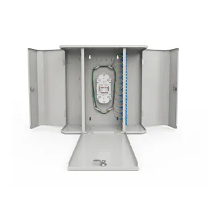
JOTB-192A Optical Terminal Box
192-port cold-rolled-steel IP65 box for high-density building entrance and outdoor distribution points.
View Product →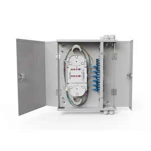
JOTB-48B Optical Terminal Box
48-port cold-rolled-steel IP65 dual-door box for MDU riser and outdoor distribution handoffs.
View Product →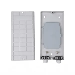
JOTB-24A Optical Terminal Box
Compact 24-port ABS IP54 box for single-family and small MDU subscriber termination.
View Product →Related Articles

Outdoor Fiber Termination Box Guide
How to choose the right outdoor fiber termination box — capacity, material, and IP rating for your deployment.
Read Article →
Fiber Optic Splice Closure Installation Guide
Step-by-step splice closure installation including cable entry, splicing, and sealing best practices.
Read Article →
FTTH Network Architecture Guide
End-to-end FTTH architecture — where FDC, FDB, splice closures, and terminal boxes sit in the PON.
Read Article →References
- ITU-T L.106 — Access infrastructure: installation of optical fibre cable for FTTH and related metallic infrastructure
- ITU-T G.984.1 — Gigabit-capable passive optical networks (GPON): General characteristics
- ITU-T G.652 — Characteristics of a single-mode optical fibre and cable (bending radius guidance)
Key takeaway
A fiber optic terminal box is only as reliable as its install. Survey the site and pick the right size and IP rating first; mount level and sealed; route and seal cable entry against water; splice clean and leave a service loop; manage every fiber along the radius path and secure it; test every port and record it. Most subscriber-side faults are not failures of the box — they are failures of the installation. Do the job once, correctly, and the box runs for the life of the network.