FTTH Network Architecture: From OLT to ONT
By Jergeo Engineering Team | Published June 2026 · 12 min read
A FTTH (Fiber to the Home) network carries data from the central office to individual subscribers over a fully passive optical path. The architecture breaks into three blocks: the active equipment at the headend (OLT), the passive optical distribution network (ODN) in the field, and the customer-premises equipment (ONT/ONU). Below, we cover each block — the fiber distribution hierarchy inside the ODN, splitter placement strategies, and the physical equipment at every segment.
Summary
An FTTH network uses a central office ODF, feeder cables to FDCs, PLC splitters in distribution boxes, and drop cables to terminal boxes. The ODN layer is entirely passive between the OLT and ONT.
PON network overview
A Passive Optical Network (PON) uses a point-to-multipoint topology. A single OLT port at the central office serves 32, 64, or 128 subscribers through a tree of optical splitters. No active electronics sit between the OLT and the ONT — the entire outside plant is passive fiber, connectors, and splitters.
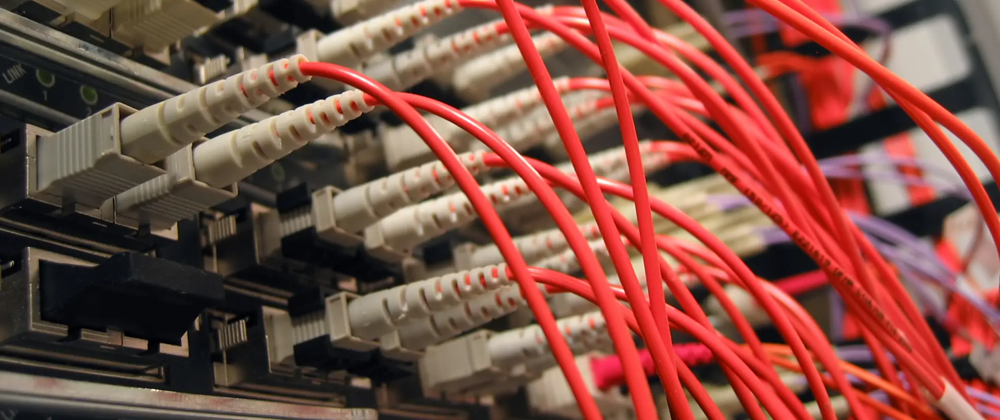
The signal path follows one direction:
OLT (Central Office) → Feeder Cable → Fiber Distribution Cabinet → Distribution Cable → Fiber Distribution Box → Drop Cable → ONT (Customer Premises)
The current PON generations in use are GPON (2.5 Gbps downstream / 1.25 Gbps upstream), XGS-PON (10 Gbps symmetric), and 25G/50G-PON (the emerging next step). The physical outside plant — cables, cabinets, splitters, terminals — stays the same across all three. Only the OLT and ONT electronics change.
ODN structure: three cable segments
The ODN (Optical Distribution Network) is the passive fiber plant between the OLT and the ONT. Industry practice divides it into three physical segments, each with its own cable type, enclosure, and function.
1. Feeder segment
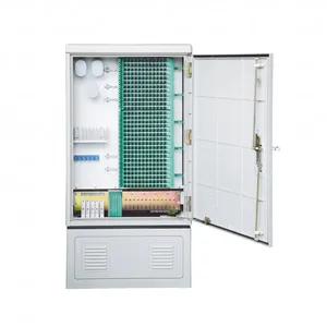
The feeder segment runs from the OLT rack in the central office to the first distribution point — typically a Fiber Distribution Cabinet (FDC) located at a cabinet site or pedestal near the subscriber area. Feeder cables carry the full fiber count for all subscribers downstream of that cabinet, so they are high-count cables (96–576 fibers). The FDC at this point performs fiber cross-connection between the feeder cable and the distribution cables that fan out to neighborhoods.
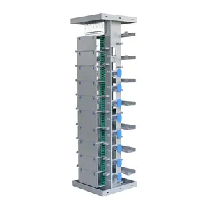
Equipment: Fiber Distribution Cabinet (FDC), and at the central office side, an Optical Distribution Frame (ODF) where the OLT ports terminate. The FDC must handle high fiber counts, provide IP65-rated outdoor protection, and support drawer-type splice trays for efficient maintenance. Jergeo's Fiber Distribution Cabinet series (JFDC-288A/B/C) offers 288-port capacity in SMC enclosures rated for −45 °C to +80 °C operation.
2. Distribution segment
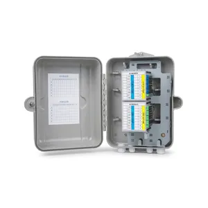
From the FDC, distribution cables (typically 12–48 fibers) run toward clusters of subscribers — an apartment building, a row of houses, or a campus block. At each distribution point, a Fiber Distribution Box (FDB) or a Fiber Splice Closure (FSC) provides the splice and branching point. The FDB serves as a mini cross-connect where distribution cables meet drop cables. A FSC performs the same role in aerial or direct-buried installations where a wall-mount box is not practical.
Equipment: Fiber Distribution Box (FDB) for wall/pole mounting, Fiber Splice Closure (FSC) for aerial or buried splice points. Jergeo's Fiber Distribution Box range covers 4–48 port configurations with SC/LC/FC adapter options, and the Fiber Splice Closure series (JFS series) provides 24–96 splice capacity in dome or inline form factors.
3. Drop segment
The drop segment is the final run from the FDB to the subscriber's wall outlet. Drop cables are single-fiber or dual-fiber, lightweight, and routed along building facades or through interior conduits. At the customer end, a Optical Terminal Box (OTB) terminates the drop cable and provides the fiber adapter that the ONT patch cord plugs into. The OTB is the demarcation point between the operator's network and the customer's premises.
Equipment: Optical Terminal Box (OTB) at the customer end, and PLC Splitter Cassettes housed inside the FDB or FDC. Jergeo's Optical Terminal Box series (JOTB-A through JOTB-F) covers 1- to 8-port configurations for indoor wall-mount installation. The PLC Splitter cassettes (1×4, 1×8, 1×16, 1×32) plug directly into the splitter tray slots inside FDBs and FDCs.
Equipment at every ODN node
The table below maps each network segment to the enclosure and component types deployed at that point.
| Network Segment | Primary Enclosure | Key Components | Typical Fiber Count | Jergeo Product Line |
|---|---|---|---|---|
| Central Office | ODF rack | ODF, splice trays, adapter panels | 48–576 per rack | ODF |
| Feeder | FDC (outdoor cabinet) | Splice trays, distribution modules | 96–576 | FDC |
| Distribution | FDB / FSC | PLC splitter, adapter holders, splice trays | 12–48 | FDB, FSC |
| Drop | OTB (indoor terminal) | Adapter, pigtails, fiber management | 1–4 | OTB |
| Splitter location | Inside FDB, FDC, or ODF | PLC splitter cassette | 1×8 / 1×16 / 1×32 | PLC Splitter |
Splitter placement: single-stage vs. two-stage
The PLC splitter is the only component in the ODN that introduces optical loss beyond what connectors and fiber length contribute. Where you place the splitter determines the architecture class and has real consequences for loss budget, fiber utilization, and maintenance complexity.
Single-stage splitting
A single splitter (typically 1×32 or 1×64) sits at the FDC in the feeder segment. Every subscriber ONT connects directly to this one splitter through a dedicated drop fiber. This architecture is simple: one splitter location, one loss calculation, one place to troubleshoot.
Single-stage works best when subscriber density is high around a single cabinet — a typical use case in dense urban neighborhoods where a 288-port FDC serves a cluster of apartment buildings within 500 m. The loss budget is straightforward: splitter insertion loss (~17 dB for 1×32, ~21 dB for 1×64) plus connector losses plus fiber attenuation over the full distance.
Two-stage splitting
A first-stage splitter (e.g. 1×4 or 1×8) sits at the FDC, and a second-stage splitter (e.g. 1×8 or 1×16) sits at the FDB closer to subscribers. The total split ratio is the product of both stages: a 1×4 followed by 1×8 gives 1×32 total.
Two-stage splitting is the default in suburban and rural deployments where a single FDC covers a wide geographic area. It lets one feeder cabinet serve multiple distribution zones — each with its own FDB and second-stage splitter — without running a dedicated fiber from the FDC to every single subscriber. The trade-off is slightly higher total insertion loss (two splitter hops instead of one) and more equipment to inventory.
Deployment topologies
The physical route that distribution and drop cables follow determines the topology. Three patterns dominate FTTH deployments.
Star topology
Each subscriber has a dedicated fiber run from the FDC (or from the splitter location) all the way back to the OLT. No intermediate splice points. This gives the lowest loss and simplest troubleshooting but consumes the most fiber. Star topology is rare outside small MDU (Multi-Dwelling Unit) deployments where the ONTs are all within one building and the fiber runs are short.
Tree topology
The standard PON topology. A feeder fiber from the OLT reaches the FDC, where splitters branch the signal into multiple distribution fibers. Each distribution fiber reaches a FDB, which branches again into drop fibers serving individual ONTs. The tree naturally matches the PON point-to-multipoint architecture and is the most common deployment worldwide.
Daisy-chain (bus) topology
Used in limited scenarios where a road or corridor has subscribers spread along a linear path. A single fiber runs along the corridor; at each FDB, a small-ratio splitter (1×2 or 1×4) taps off a portion of the optical power for local subscribers while passing the remaining power downstream to the next FDB. This saves fiber but accumulates splitter loss at each tap point, limiting the total number of subscribers per OLT port.
Loss budget considerations
GPON Class B+ OLTs support a maximum channel insertion loss of 28 dB. XGS-PON extends this to approximately 30–32 dB depending on the power class. The ODN loss budget must account for every element in the path:
- PLC splitter loss: ~7 dB (1×4), ~10.5 dB (1×8), ~14 dB (1×16), ~17 dB (1×32), ~21 dB (1×64)
- Connector loss: ≤0.3 dB per mated pair (SC/APC or LC/UPC); typical 0.15–0.20 dB with good installation practice
- Splice loss: ≤0.05 dB per fusion splice; 4–8 splices are typical in a tree topology
- Fiber attenuation: 0.35 dB/km at 1310 nm, 0.20 dB/km at 1490/1550 nm (G.652.D single-mode fiber)
With a 1×32 splitter (~17 dB), 6 connectors (~1.2 dB), 6 splices (~0.3 dB), and 5 km of fiber at 1550 nm (~1.0 dB), total ODN loss comes to roughly 19.5 dB — well within the 28 dB GPON Class B+ budget. This is why 1×32 remains the most common split ratio for GPON: it balances subscriber density with comfortable margin.
Equipment selection checklist for FTTH deployment
When specifying ODN equipment for a FTTH project, verify these parameters for each enclosure type:
Fiber Distribution Cabinet (FDC)
- Port capacity (144 / 288 / 576) must match the feeder cable count plus spare capacity
- IP65 minimum for outdoor deployment; SMC shell material for corrosion resistance
- Drawer-type tray structure for splice-and-distribution integration
- Splitter tray slots available if the FDC also houses the first-stage splitter
- Working temperature range suitable for the deployment climate (−45 °C to +80 °C covers most regions)
Fiber Distribution Box (FDB)
- Port count matched to the number of drop fibers served from that point
- Splitter cassette slot for second-stage splitter (if using two-stage architecture)
- Adapter type (SC, LC, or FC) consistent with the operator's patch cord standard
- Wall-mount or pole-mount options depending on installation site
Fiber Splice Closure (FSC)
- Splice capacity (24/48/96/144) sized for feeder-to-distribution cable splicing plus future re-entry
- Dome type for aerial/pole mounting; inline type for direct-buried installation
- Re-entry capability: the closure must be openable for fiber reassignment without replacing the housing
Optical Terminal Box (OTB)
- 1–4 ports for single-family homes; 4–8 ports for small MDUs
- Indoor-rated material (ABS plastic) with SC/APC or LC/UPC adapter
- Compact form factor for wall mounting near the ONT location
ODF (Optical Distribution Frame)
- Rack-mount format (19" standard) for central office integration
- High-density configuration: 48–144 ports per 1U panel
- Both splice and termination capability for OLT pigtail-to-feeder cable cross-connect
Scaling from GPON to XGS-PON
One of the architectural advantages of PON is that the ODN does not change when upgrading from GPON to XGS-PON. The same fiber, the same cabinets, the same splitters, and the same enclosures carry both signals. The upgrade requires only swapping OLT line cards at the central office and ONTs at the customer premises.
This is why getting the outside plant right matters more than the electronics choice. A well-designed ODN with properly specified FDCs, FDBs, splitters, and OTBs will serve the network for 20+ years across multiple technology generations. The OLT and ONT will be replaced at least twice in that period; the ODN equipment should not.
Supporting components
Beyond the primary enclosures, several component types populate the inside of every FDC, FDB, and ODF:
- Splice & Distribution Modules: Combine splice protection and adapter termination in a single slide-out module. Used inside FDCs and FDBs for organized fiber management.
- Fiber Splice Trays: Stackable trays that hold fusion splice protectors and organize the excess fiber slack. Available in multiple form factors (round, rectangular) to fit different enclosures.
- Adapter Holders: Snap-in plastic holders that secure SC/LC/FC adapters in the front panel of FDBs and OTBs.
- Cable Management Accessories: Routing rings, cable ties, and heat-shrink splice protectors maintain bend radius and protect individual splices inside every enclosure.
Jergeo manufactures the full range of these supporting components — Splice & Distribution Modules, Fiber Splice Trays, and Plastic Accessories — designed to fit inside the company's own enclosure product lines, ensuring dimensional compatibility across the entire ODN chain.
Related Products
References
- ITU-T G.984 — Gigabit-capable Passive Optical Network (GPON) standard
- The Fiber Optic Association (FOA) — fiber optic technology reference and training resources
- Fiber Broadband Association — FTTH market data, deployment research, and industry standards
Key takeaway
The FTTH network is only as reliable as its weakest passive component. Design the ODN around three clear segments — feeder, distribution, and drop — with the right enclosure at each node. Choose single-stage splitting for dense urban areas and two-stage for suburban or rural coverage. Specify IP65-rated SMC cabinets outdoors, properly sized splitters, and maintain at least 8 dB of loss margin for future technology upgrades. The outside plant you build today should outlast two or three generations of active electronics.
Related products
Related Articles

Fiber Optic Splitter Guide
PLC splitter types, ratios, and selection criteria for FTTx network design.
Read Article →
ODN Equipment Complete Guide
Complete list of all passive fiber network components and their roles in the ODN.
Read Article →
Fiber Distribution Cabinet Buying Guide
How to spec the right FDC for each level of the FTTH network hierarchy.
Read Article →