How to Choose a Fiber Distribution Cabinet for Outdoor Deployment
By Jergeo Engineering Team | Last updated July 2025 · 9 min read
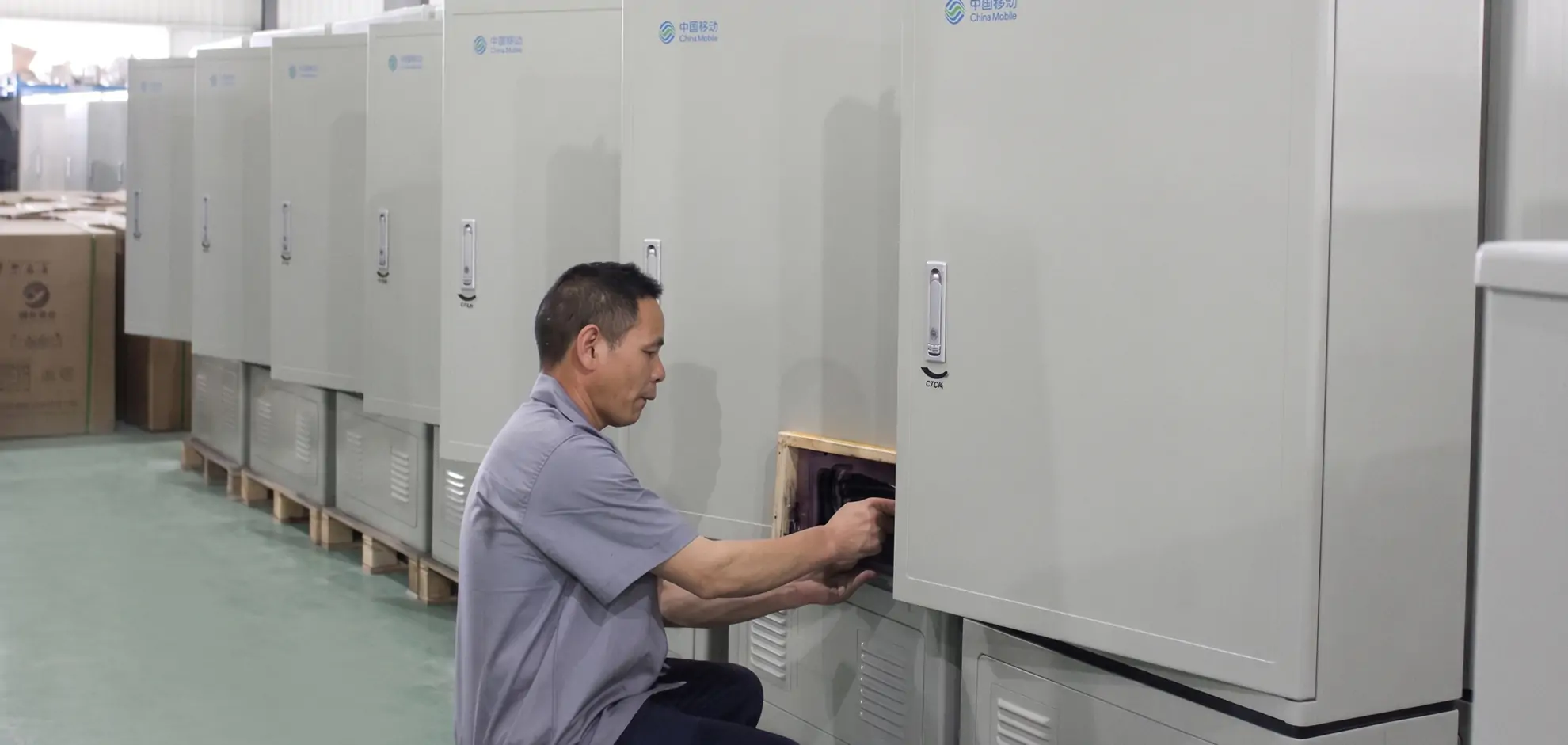
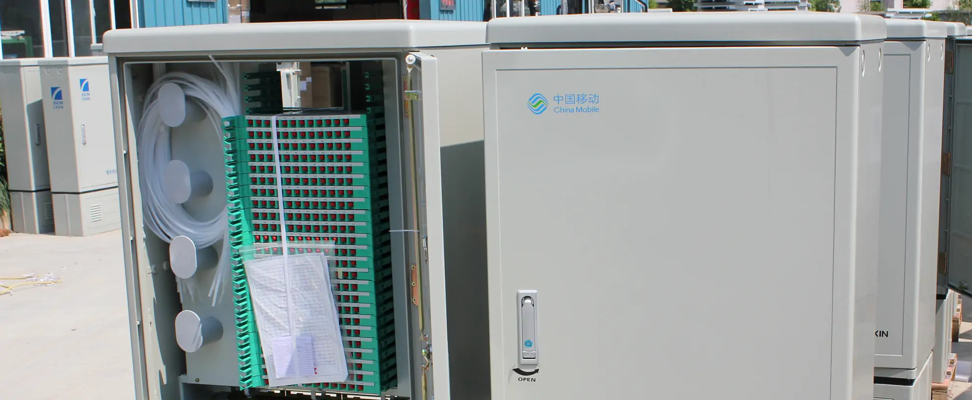
A fiber distribution cabinet — sometimes called a fiber distribution hub — sits at the boundary between the feeder network and the drop network in an FTTx deployment. It receives trunk cables from the central office or remote terminal, houses splice points and splitters, and routes individual fibers to subscriber premises. Picking the wrong cabinet at the design stage means paying for rework later: a unit that's too small forces you to stack extra enclosures on the same pole, while oversized cabinets increase upfront cost and take up space you may not have.
Summary
Choose an FDC based on port capacity (with 20-30% growth margin), outdoor IP65 rating, SMC material for UV resistance, and drawer-type splice modules for easier maintenance in the field.
This guide covers the engineering decisions that actually matter when specifying an outdoor fiber distribution cabinet: capacity planning, material selection, IP protection, cable entry, and splitter integration. Specifications referenced throughout are drawn from the Jergeo JFDC product line.
What is a fiber distribution hub and where does it go
In a PON (Passive Optical Network) topology, the fiber distribution hub is the node where feeder cables meet distribution cables. It typically sits at a street corner, on a building wall, or mounted on a utility pole — anywhere between the central office splitter location and the end user's premises.
Its job is straightforward: provide a weatherproof enclosure that protects fiber splices and splitter modules from rain, dust, UV radiation, and temperature swings, while giving technicians enough physical room to route, splice, and patch fibers without bending them past their minimum bend radius.
Typical deployment locations include:
- Residential neighborhoods (serving 72–288 homes per cabinet)
- Commercial districts with high subscriber density (288–1152 ports per cabinet)
- Roadside points where long-haul feeder cable meets short-drop distribution runs
- Building entrances in multi-dwelling unit (MDU) installations
Capacity planning: 72 to 1152 ports
Fiber distribution cabinets come in standard capacity tiers. The right size depends on your subscriber count per serving area, your splitter ratio (typically 1:32 or 1:64 in GPON), and how much spare capacity you want to leave for future connections.
| Capacity | Typical Use Case | Cabinet Dimensions | Example Model |
|---|---|---|---|
| 72 ports | Small rural clusters, MDU entrances | 780×450×280mm | JFDC-72A |
| 144 ports | Street-level distribution, small neighborhoods | 780×450×280mm to 1035×555×310mm | JFDC-144A / 144B |
| 288 ports | Medium residential areas, campus distribution | 1450×750×360mm to 1550×750×360mm | JFDC-288A / 288B |
| 576 ports | Dense urban deployment, commercial districts | 1450×753×620mm to 1550×1450×360mm | JFDC-576A / 576B |
| 1152 ports | High-density urban cores, aggregation points | 1550×1450×620mm | JFDC-1152A |
How to calculate the right capacity for your project:
- Start with subscriber count. If you need to serve 200 homes with a 1:32 splitter ratio, you need 200 distribution fibers plus spare. A 288-port cabinet (like the JFDC-288 series) gives you 288 ports with 88 ports of spare capacity.
- Account for splitter modules. Each splice & distribution module in the JFDC series holds adapter panels for FC/SC/LC connectors. The JFDC-288A ships with 24 modules; the JFDC-576A and 576B ship with 48; the JFDC-1152A carries 96 modules.
- Plan for 20–30% growth. Fiber networks outlast the demand forecasts that sized them. If your initial build serves 250 homes, a 576-port cabinet gives room to expand without deploying a second enclosure.
Material comparison: SMC vs stainless steel
The shell material determines how the cabinet handles impact, corrosion, UV exposure, and temperature swings over a 20+ year service life. Two materials dominate the outdoor fiber distribution cabinet market: SMC (Sheet Molding Compound) and stainless steel.
| Property | SMC (Sheet Molding Compound) | Stainless Steel |
|---|---|---|
| Composition | Glass-fiber reinforced polyester composite | Corrosion-resistant steel alloy |
| Weight | Lighter — easier wall/pole mounting | Heavier — requires ground mounting |
| Corrosion resistance | Inherent — no coating needed | Excellent in most environments |
| Impact resistance | Good — composite flexes under impact | Very good — rigid and dent-resistant |
| UV resistance | Good — material is UV-stable throughout | Not a concern |
| Temperature range | −45°C to +80°C | −45°C to +80°C |
| Internal structure | Metal frame | Stainless steel frame |
| Cost | Lower material cost | Higher material cost |
| Best for | Wall/pole mount, coastal areas, general deployment | High-vandalism areas, industrial zones |
In the Jergeo JFDC line, SMC is the standard material used across the 72-port, 144-port, 288-port, and most 576-port models. Stainless steel is offered for the JFDC-288E (288 ports), JFDC-144C (144 ports), and JFDC-576F (576 ports). The stainless steel variants use a full stainless steel shell and internal structure — not just a steel frame inside an SMC housing — making them suitable for installations where mechanical abuse is a realistic concern.
Both materials maintain IP65 protection across the same −45°C to +80°C operating range, so temperature alone doesn't determine your choice. The deciding factors are mounting method (SMC's lighter weight allows wall/pole mounting; stainless steel units are typically ground-mounted) and vandalism risk.
IP rating: what IP65 actually protects against
Every model in the JFDC series is rated IP65. The two digits carry specific meaning:
- First digit (6): Complete protection against dust ingress. No seal degradation over the cabinet's service life.
- Second digit (5): Protection against water jets from any direction. Rain, spray from street cleaning, hose-down during maintenance — none of it reaches the fiber inside.
This matters because outdoor fiber optic cabinets face conditions that indoor patch panels never encounter. Condensation forms inside the enclosure during temperature cycling. Wind-driven rain hits seams at angles that test gasket compression. Dust and sand infiltrate poorly sealed joints and coat fiber surfaces, increasing insertion loss.
The JFDC series achieves IP65 through compression gaskets on all doors and cable entry points, worm-gear pipe clamps on cable entries (rated φ9–16mm and φ16–25mm depending on model), and sealed cable gland ports in the bottom section of the cabinet. All models also specify operation at ≤95% relative humidity (at 40°C) and air pressure from 70 to 106 kPa, which covers installations at altitudes up to approximately 3,000 meters.
If your deployment environment requires submersion resistance (flood-prone areas) or high-pressure wash-down protection, you would need IP67 or IP66 respectively. For standard outdoor telecom deployments, IP65 is the industry baseline and is sufficient.
Cable entry and fiber management
Cable management inside an outdoor fiber optic cabinet determines how fast a technician can find, trace, and patch a fiber during maintenance. Poor routing turns every service call into a 30-minute spelunking expedition.
The JFDC series uses a drawer-type tray structure with dedicated splice and distribution modules. Each model's configuration includes:
- Splice & distribution modules: 6 modules (JFDC-72A) up to 96 modules (JFDC-1152A). Each module accepts FC/SC/LC adapters and provides a dedicated routing path for pigtails and patch cords.
- Cable entry clamps: Worm-gear pipe clamps at the bottom section secure incoming cables. The JFDC-72A provides 4 clamps (φ9–16mm ×2, φ16–25mm ×2); the JFDC-1152A provides 60 clamps (φ9–16mm ×40, φ16–25mm ×20). This range covers most standard fiber cable outer diameters used in FTTH networks.
- Fiber protection tubes: Heat-shrink or spiral wrap tubes protect individual fibers at splice points. The JFDC-72A includes 8m; the JFDC-1152A includes 32m. These are sized proportionally to the number of splice points.
- Cable ties: Plastic cable ties (150×4mm standard) secure fibers to routing guides within each module.
The bottom section of each cabinet (350mm height on most models) serves as the cable entry and grounding zone. Cables enter through sealed glands in this section, get anchored by the worm-gear clamps, and then route upward into the body section where splice trays are housed. This physical separation between the cable entry zone and the splice zone prevents cable pull forces from stressing splice points.
Splitter integration options
In a PON architecture, the optical splitter divides one upstream signal into multiple downstream signals (and combines multiple upstream signals into one). Splitters are typically housed inside the fiber distribution hub in one of two configurations:
- Splitter in the FDC: The cabinet houses PLC splitter cassettes alongside splice trays. This is common in centralized splitting architectures where the splitter sits at the serving area boundary. All JFDC models support this — the splice & distribution modules accept both splice sleeves and splitter cassettes.
- Splitter in a separate enclosure: The FDC acts purely as a pass-through splice and distribution point, with the splitter housed upstream. This is common in distributed splitting architectures or when splitter location flexibility is needed.
The adapter options (FC, SC, or LC) on each JFDC module let you match the connector type used in your splitter cassettes and drop cables. The modules are field-configurable, so you can mix connector types within the same cabinet if your network uses different connector standards in different segments.
Mounting considerations: ground vs wall vs pole
Not every mounting method works with every cabinet. The physical weight and dimensions of the enclosure constrain your options:
- Ground/Wall mounting: Available on the JFDC-72A, 144A/144B, 288A/288B/288C/288D series. These SMC models are light enough for wall brackets or pole straps. The 72-port model at 780×450×280mm fits easily on a building wall or utility pole.
- Ground mounting only: The 576-port and 1152-port models, plus all stainless steel variants, require ground-level installation on a concrete pad. Their size and weight make wall or pole mounting impractical. The JFDC-1152A at 1550×1450×620mm with 4 doors (front and rear) is essentially a small walk-in enclosure.
When choosing a mounting location, consider technician access height, vehicle proximity for cable reel placement, and drainage — the bottom cable entry section should sit above the highest expected water level.
Door configuration and maintenance access
Door layout affects how technicians work inside the cabinet. Single-door designs (used on all 72-port, 144-port, and most 288-port models) require the technician to work from one side, which is fine for smaller cabinets where everything is within arm's reach.
Dual-door designs — doors on front and rear (used on JFDC-576B, 576C, 576D) — let one technician work on splices from the front while cable entries and grounding connections are accessed from the rear. This matters on larger cabinets where depth exceeds 500mm and reaching through a single door to the back panel is awkward.
The JFDC-1152A takes this further with 4 doors (front and rear), essentially creating a walk-around configuration for the highest-capacity unit in the series. At 1550×1450×620mm, it needs that access pattern — the 96 splice & distribution modules and 60 cable clamps create enough internal work that single-side access would be impractical.
Related Products
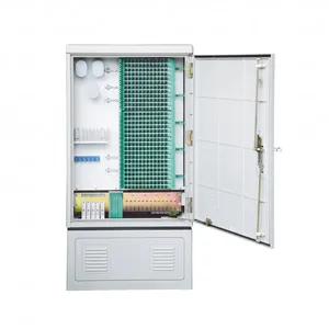
JFDC-288A Fiber Distribution Cabinet
288 ports FDC with wall/pole mounting options
View Product →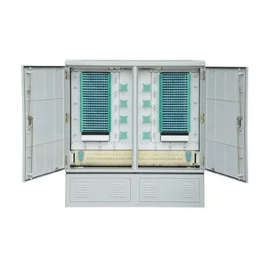
JFDC-576A Fiber Distribution Cabinet
576 ports FDC with dual-door design and SMC material
View Product →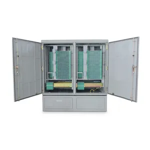
JFDC-1152A Fiber Distribution Cabinet
High-capacity 1152 ports fiber distribution cabinet with SMC material
View Product →References
Key takeaway
Start with your subscriber count and splitter ratio to size the cabinet — then add 20–30% spare capacity for growth. SMC is the default material for most deployments (lighter, cheaper, wall-mountable); choose stainless steel only when vandalism risk or industrial environment demands it. IP65 is the standard protection level for outdoor FTTH cabinets. Pay attention to cable entry clamp count and door configuration — these determine field maintenance efficiency far more than the port count on the datasheet.
Related products
Related Articles
FDC vs FDH vs ODC: What's the Difference?
Understand the three naming conventions for fiber cabinets and how to choose by function.
Read Article →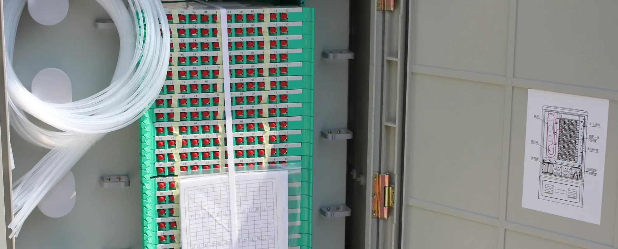
Fiber Cabinet Materials: SMC vs Steel vs ABS
Weight, IP rating, UV resistance, temperature range, cost, and lifespan compared for the three main enclosure materials.
Read Article →
How to Install Splice Trays in an FDC
Step-by-step field guide for installing and organizing splice trays in fiber distribution cabinets.
Read Article →