Fiber Optic Network Expansion: A Practical Capacity Planning Guide
By Jergeo Engineering Team | Updated September 2026 · 12 min read
Every fiber optic network expansion we have worked on follows the same pattern: someone underestimates how fast the network will grow. A 144-port FDC that seemed generous at deployment fills up in 18 months. A feeder cable with exactly enough fibers for the planned splitter ratio leaves zero room for a second PON tree. Then the expansion becomes an expensive retrofit instead of a planned upgrade.
This guide covers how to plan capacity at every layer of the fiber network — from the FDC at the distribution point to the termination box at the subscriber premises. The numbers and strategies come from actual FTTH and ISP deployments we have supplied equipment for across Southeast Asia, the Middle East, Africa, and Latin America.
Summary
A successful fiber optic network expansion depends on three decisions made during initial deployment: how much spare capacity to build in at each node (25-30% port spare, 20% splice spare), which equipment form factor accommodates future growth without replacement (modular FDCs, high-density ODFs, large-capacity FDBs), and how to phase spending so that upfront CAPEX stays manageable while leaving clear upgrade paths. This guide walks through the math, the product selection logic, and the phased deployment approach that works in practice.
Why Expansion Planning Determines Your CAPEX
The cost difference between planning for expansion and retrofitting later is not subtle. From what we have seen across dozens of deployments, a network that was designed with growth in mind costs 35-45% less over a 5-year period than one that got expanded reactively.
Here is where the money goes when you skip planning:
- Emergency hardware procurement — ordering a replacement 576-port FDC because the 288-port unit is full costs 2-3x more per port than buying the 576-port unit initially. The per-port price difference between a JFDC-288A and a JFDC-576A is roughly 30%, but you get double the capacity.
- Civil works duplication — digging up a trench to pull additional fiber, mounting a second cabinet foundation, or drilling new cable entry paths. These costs often exceed the hardware cost itself.
- Service disruption — swapping out a full cabinet means disconnecting every subscriber on that node. In a commercial area with SLA commitments, the cost of downtime can dwarf the equipment savings.
- Customer acquisition delays — every week a distribution node is at capacity is a week where new subscribers cannot be connected. In competitive markets, that is revenue going to the operator next door.
The operators who get this right treat expansion capacity as a design parameter, not an afterthought. They specify it in the procurement document and hold vendors to it.
How to Calculate Capacity Requirements
The capacity calculation needs to happen at three levels: port count, splice count, and physical space. Each has its own margin rules.
Port Capacity: The 25-30% Rule
Start with your target subscriber count at full build-out — not your current subscriber count. Then add 25-30% for spare ports. This spare capacity serves multiple purposes: subscriber growth beyond the original plan, service diversification (business lines, backhaul for cell towers), and port failures that need bypass.
Practical example: if your distribution node serves a neighborhood with 200 planned premises, you need at minimum:
- 200 ports for subscribers
- 50-60 spare ports (25-30% margin)
- Total: 250-260 ports minimum
This points to a 288-port FDC as the right starting point — like the JFDC-288A with 288 ports. If the neighborhood has 250+ planned premises, step up to a 576-port FDC rather than planning to add a second 288-port cabinet later.
Splice Point Capacity: Plan for 20% Spare
Every splice closure and every splice tray inside a cabinet needs spare positions. The rule we follow: 20% unused splice positions in every enclosure. This accounts for fiber damage during construction, re-splicing due to high-loss events, and future branch connections.
For a 144-fiber cable termination, you need a closure rated for at least 173 splices (144 × 1.2). In practice, this means selecting a 288-fiber splice closure rather than a 144-fiber one. The 288-port closure gives you 100% spare capacity — more than the 20% minimum — but the cost difference is small compared to the installation cost of replacing an undersized closure later.
Physical Space: The Overlooked Constraint
Ports and splices are easy to count. Physical space is where plans fall apart. A cabinet that has all 288 ports populated but zero room for additional splitter trays or management accessories is effectively at capacity, even though the port count technically matches.
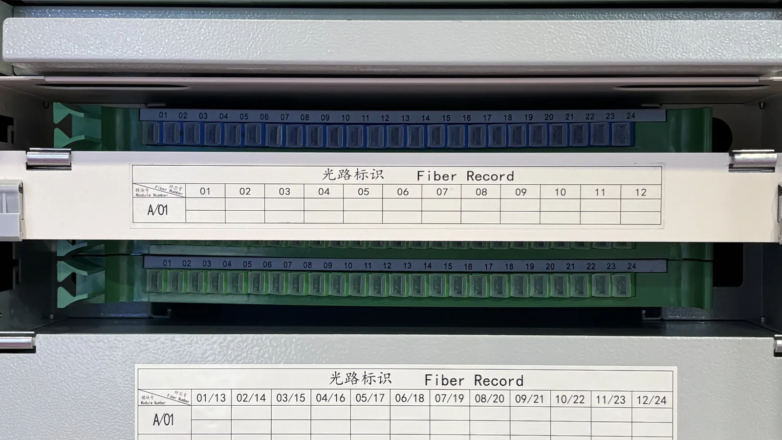
The fix: when selecting enclosures, count the number of tray positions and plan to use no more than 70-75% of them during initial deployment. The remaining slots hold future splitters, additional adapter panels, or cable management trays. For the JFDC-288 series with 24 splice and distribution modules, this means installing a maximum of 17-18 modules initially and keeping 6-7 positions open for expansion.
Product Selection for Expansion-Ready Networks
Different products at different network layers have different expansion strategies. Here is how to approach each one.
Fiber Distribution Cabinet (FDC): The Distribution Node
The FDC is the most critical expansion point because replacing it is the most expensive. When selecting an FDC for a growing network:
- Choose drawer-type modular design — the JFDC-288A and JFDC-576A both use drawer-type splice trays that can be individually added, removed, or reconfigured without disturbing the rest of the cabinet. This is essential for live-network expansion.
- Select one size step above your immediate need — if 144 ports covers today's demand, order the 288-port model. The price delta is typically 15-25%, but you eliminate a full cabinet replacement in 2-3 years.
- Reserve internal structure positions — the cabinet's internal metal frame usually has mounting positions for additional tray stacks. Confirm these exist and are accessible before populating the cabinet.
- For high-growth areas, go directly to 576 or 1152 ports — the JFDC-1152A serves large aggregation points where subscriber density justifies the larger footprint.
Optical Distribution Frame (ODF) / Fiber Patch Panel: The Central Office
At the central office or exchange, the ODF is your main cross-connect point. Expansion here means adding ports and managing more patch cords in limited rack space.
- Choose high-density form factors — the JODF-C2 delivers 1440 ports in a single rack-mount frame. High density means you do not need to add rack units as the network grows.
- Reserve adapter panel positions — if the ODF has space for 12 adapter panels, install 8-9 initially. The empty positions let you add more panels without re-wiring the backbone cable entry.
- Separate backbone and distribution cable management — this sounds obvious, but we have seen ODFs where backbone cables and distribution patch cords are tangled together. When expansion time comes, nobody can tell which fiber goes where. Label everything during initial deployment.
Fiber Distribution Box (FDB) / Fiber Termination Box: The Access Point
The FDB sits closest to the subscriber — at building entry points, in basements, or on building facades. These are the units where capacity shortages create the most visible customer impact.
- Choose larger enclosures for new construction — a 96-port FDB costs only marginally more than a 48-port unit. In new residential developments where subscriber ramp-up is predictable, always go larger.
- Reserve splitter positions — if the FDB has 4 splitter slots, populate 3 initially. The fourth slot is your expansion path when you need to add a second PON split or reconfigure the split ratio.
- For retrofits, consider the JFDB-64A — its 64-port capacity in a compact enclosure works well for infill expansion in areas where the original FDB is full but space for a second enclosure is limited.
Other Products That Support Expansion
- Monitoring Cabinets (JMC series) — the JMC-A through JMC-D provide centralized monitoring of network performance. When planning expansion, ensure the monitoring cabinet has spare input channels for the additional fibers you will add in later phases.
- Network Cabinets (JNC series) — the JNC-A 42U at the aggregation point should follow the same 25% spare U-height rule as any rack installation.
- Optical Terminal Boxes (JOTB series) — for subscriber-side termination, select the JOTB-48B (48 ports) over the 24-port or 12-port models for new multi-dwelling units. The incremental cost is small; the avoided truck roll for a future upgrade is not.
Phased Deployment Strategy: The 60-80-100 Approach
Rather than deploying 100% capacity on day one (which ties up capital in unused ports), a phased approach matches spending to actual subscriber ramp-up. Here is how the three phases work in practice:
Phase 1: Initial Deployment (60% capacity populated)
Install the full enclosure infrastructure at rated capacity — the 576-port FDC, the conduit, the feeder cable. But only populate 60% of the ports with active patch cords and splitters. This gives you the full physical plant in place while the fiber electronics and patch cords reflect only 60% of the cost.
The key insight: the enclosure (cabinet, conduit, foundation) is the expensive part. The ports and patch cords are cheap by comparison. Deploy the expensive part once; add the cheap part in phases.
Phase 2: Growth Phase (80% capacity)
As subscriber uptake reaches 50-60%, activate the remaining reserved ports. This typically happens 12-24 months after initial deployment in urban areas, or 24-36 months in suburban/rural areas.
At this stage, you may also add splitter cassettes in the reserved tray positions. The cabinet stays the same — only the internal configuration changes.
Phase 3: Full Build-Out (100% capacity + expansion planning)
When the node approaches 85-90% utilization, it is time to plan the next expansion. This could mean adding a second FDC at the same site, upgrading to a higher-capacity model, or splitting the service area into two nodes.
The critical step: start planning 3-6 months before you actually need the capacity. Lead times for large FDCs can run 4-8 weeks, and civil works for a new cabinet foundation take another 1-2 weeks.
Common Mistakes to Avoid
Mistake 1: Exact-Match Sizing
Ordering a 144-port FDC for exactly 144 planned subscribers leaves zero margin. Port failures, fiber damage, and unexpected demand from a new apartment block will push you over capacity before the network is even commissioned. Always round up to the next standard size — 144 planned subscribers means a 288-port cabinet.
Mistake 2: Over-Reserving
The opposite problem is also real. We have seen operators install 1152-port FDCs in areas with 200 planned premises "just in case." The capital tied up in unused ports could have been deployed to extend the network to the next neighborhood. The 25-30% margin rule balances readiness against cost.
Mistake 3: Ignoring the Feeder Cable
The feeder cable between the central office and the FDC is the hardest component to upgrade. Pulling additional fiber through an existing conduit is possible but expensive — typically 5-10x the cost of installing the fiber during initial construction. Always install 30-50% more fiber in the feeder than the initial deployment requires. The incremental fiber cost is small relative to the trenching and conduit cost.
Mistake 4: Forgetting About Technology Migration
If your initial deployment uses GPON (1:64 split), and you plan to migrate to XGS-PON or NG-PON2 in 3-5 years, the splitter ratio and wavelength plan will change. This affects the number of splitter trays needed and the type of adapter panels. Choose equipment that is agnostic to the PON generation — modular FDCs with swappable tray configurations handle this transition without enclosure replacement.
Mistake 5: No Documentation
When expansion time comes, the installation crew needs to know what is where. If the initial deployment was done without proper labeling — which tray holds which fiber, which adapter panel serves which street — expansion becomes a forensic investigation. Label every tray, every fiber, every port during commissioning. The time cost is 2-3 hours per cabinet. The time saved during expansion is measured in days.
Recommended Products for Network Expansion
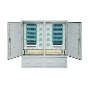
JFDC-576A Fiber Distribution Cabinet
576-port modular FDC — ideal for mid-size distribution nodes with expansion headroom
View Product →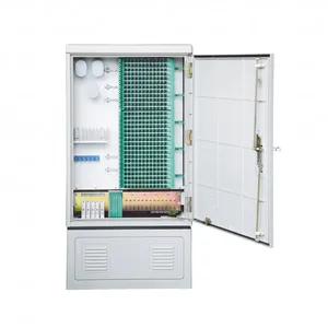
JFDC-288A Fiber Distribution Cabinet
288-port SMC cabinet with drawer-type trays — the workhorse of FTTH distribution
View Product →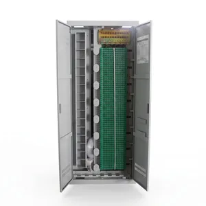
JODF-C2 Optical Distribution Frame
1440-port rack-mount ODF — high-density cross-connect for central office expansion
View Product →Related Articles
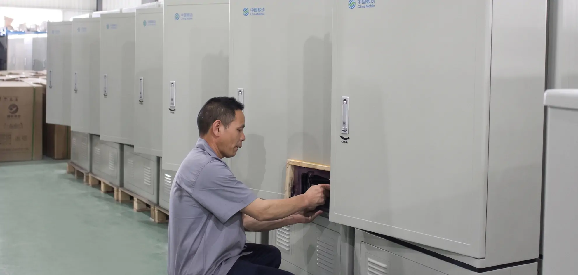
Fiber Distribution Cabinet Buying Guide
Capacity planning, material selection, and IP rating for FDC procurement decisions.
Read Article →
FTTH Network Architecture Guide
Complete FTTH architecture from OLT to ONT — understand where each distribution node fits.
Read Article →
Outdoor Fiber Termination Box Guide
Capacity, IP rating, and mounting options for the last-mile fiber termination enclosure.
Read Article →References
- ITU-T G.984 — Gigabit-capable Passive Optical Networks (GPON)
- FOA Reference Guide to FTTH Network Design — capacity planning and split ratio calculations
- BBF TR-392 — FTTx PON Equipment Requirements — includes expansion and scaling guidelines
Key takeaway
Plan for where the network will be in 3 years, not where it is today. Build the physical plant — cabinets, conduits, feeder fiber — at full capacity on day one. Populate the ports and electronics in phases to match subscriber ramp-up. And always, always leave spare positions in every enclosure. The cost of spare capacity during initial deployment is a fraction of the cost of retrofitting a full cabinet. This is the difference between a network that grows smoothly and one that requires emergency procurement at 2x the price.
Related products