Fiber Splice Closure Installation: A Step-by-Step Field Guide
By Jergeo Engineering Team | Updated June 2026 · 12 min read
This guide walks through the full installation of a fiber optic splice closure — from the moment you pull the cable out of the reel to the final OTDR trace. It covers both horizontal (inline) and dome (vertical) closures, with specific references to Jergeo models like the JFSC-L144A (silicone rubber sealed horizontal closure) and the JFSC-T96A (dome closure). Every step reflects what actually happens on a job site, not what a spec sheet says should happen.
Summary
Installing a fiber splice closure involves cable preparation, grounding, fiber routing through splice trays, fusion splicing, and sealing. IP68-rated closures require mechanical seals and heat-shrink boot installation.

Pre-installation checklist
Before heading to the splice point, verify you have everything. Forgetting a single heat shrink sleeve or the wrong size cable gland means a return trip — and in underground vaults or aerial pole work, that is not something you want.
Tools
- Fiber cleaver (high-precision, ≤0.5° cleave angle)
- Fusion splicer with appropriate program loaded for the fiber type
- Cable stripping tool — jacket stripper and buffer tube stripper
- Aramid yarn (Kevlar) scissors or cutter
- Cleaning supplies: isopropyl alcohol (≥99%), lint-free wipes, fiber inspection scope
- Heat gun (for heat-shrink sealing closures)
- OTDR or optical power meter for post-installation testing
- Cable ties, Velcro straps, marker tape, and labeling materials
- Torque wrench (if closure uses bolt-type sealing)
- Silicone grease (for O-ring lubrication on silicone-rubber-sealed closures)
Materials
- Splice protection sleeves (heat shrink type with stainless steel reinforcement rod)
- Splice trays matching the closure model (e.g., Jergeo JST-series trays)
- Cable entry port grommets or plugs sized for the incoming cable diameter
- Sealing material per closure type — silicone rubber strips, melt glue, or self-adhesive tape
- Grounding kit if required by local code (metallic cable armor grounding)
Cable preparation notes
Confirm cable type (loose tube vs. tight-buffered), fiber count, and outer diameter before opening the closure. The JFSC-L144A accepts cables with Φ7–22mm outer diameter through its 2 inlet / 2 outlet ports. The dome-style JFSC-T96A handles Φ10–22mm through 2 inlet / 2 outlet ports. If your cable falls outside these ranges, you need a different closure or adapter bushings.
Leave enough slack cable on both sides — typically 1.5 to 2 meters of extra fiber per side for routing into splice trays. For a 144-fiber closure like the JFSC-L144A, plan for approximately 2.5 meters of jacket removal per cable end.
Step-by-step installation procedure
Step 1: Cable entry and jacket stripping
Cut the outer jacket back to the planned length. Use a rotary cable stripper set to the jacket depth — do not score past the jacket into the buffer tubes. For a 48-fiber loose-tube cable, you will typically strip 1.5–2 meters of jacket. Remove the aramid yarn strength members and trim them, leaving enough to anchor under the cable clamp inside the closure. Clean the exposed buffer tubes with a lint-free wipe dampened with isopropyl alcohol.
Step 2: Open the closure body
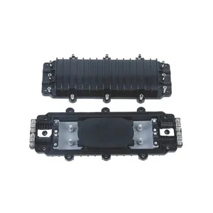
For the JFSC-L144A horizontal closure: loosen the stainless steel band clamps on both ends, separate the top half from the bottom half, and set the O-ring aside on a clean surface. The PC body is reusable, so handle it carefully — do not drop it or let it sit on gravel.
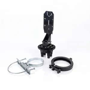
For the JFSC-T96A dome closure: remove the top dome by unscrewing the cap or unclipping the band ring depending on the sealing variant. The dome body sits inverted during the splicing process so water cannot pool on top after installation.
Step 3: Install cable entry port grommets
Thread each cable through its designated entry port. Install the rubber grommet or cable gland that matches the cable diameter. The grommet must seal tightly around the cable — if you can pull the cable by hand after the grommet is in place, the seal is not adequate. On the JFSC-L144A, the 2 inlet and 2 outlet ports accept cables from Φ7 to 22mm; use the appropriate grommet size from the kit. Unused ports must be sealed with blank plugs provided in the closure kit — never leave a port open.
Step 4: Secure cables to the closure base
Anchor the aramid yarn strength members under the internal cable clamp. Tighten the clamp firmly — the splice joint must not bear any mechanical load from the cable. Pull gently on the cable to confirm it is secure. Route the cables along the cable routing channel in the closure base. Keep the strength members separate from the fiber — they have no place in the splice area.
Step 5: Strip buffer tubes and prepare fibers
Strip the buffer tubes using a tube stripper set to the tube diameter. Wipe each fiber clean with alcohol. Slide the heat shrink splice sleeves onto the fibers before splicing — this is the most commonly forgotten step. If you are working with 12-fiber ribbon, use ribbon-compatible sleeves. Organize the fibers by color code (TIA-598 standard: blue, orange, green, brown, slate, white, red, black, yellow, violet, rose, aqua).
Step 6: Fusion splice and apply protection sleeves
Splice fibers in sequence, tray by tray. After each splice, slide the heat shrink sleeve over the splice point and place it in the splicer's heater. Typical heating time is 30–40 seconds. The sleeve must fully shrink with the reinforcement rod centered over the bare fiber splice. Visually inspect each sleeve — no air bubbles, no gaps, no kinked fiber. Store the sleeved splice in the designated slot on the splice tray.
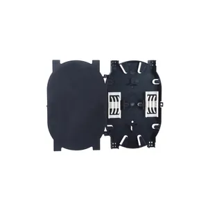
For a 144-fiber closure like the JFSC-L144A, you will fill up to 6 splice trays (each holding up to 24 fibers). Work systematically: complete one tray, verify all splices, then move to the next.
Step 7: Load splice trays into the closure
Route the fiber slack into the splice tray following the tray's fiber routing channel. The minimum bend radius is 30mm — any tighter bend will cause macrobending loss, which will show up on your OTDR trace as excess attenuation. Stack the trays into the closure body. On horizontal closures like the JFSC-L144A, trays stack horizontally on the base. On the dome closure JFSC-T96A, trays mount in the tray holder ring inside the dome body.
Confirm that no fiber is pinched between trays or pressed against the closure wall. Every fiber should have a gentle curve with no sharp bends or tension points.
Step 8: Seal the closure
The sealing method depends on the closure model:
- Silicone rubber sealing (JFSC-L144A, JFSC-L144B): Clean the O-ring groove, apply a thin film of silicone grease to the O-ring, seat the O-ring evenly in the groove, and bolt the top half onto the base. Tighten bolts in a star pattern (opposite corners first) to ensure even compression. Torque to manufacturer specification — typically 2–3 Nm for PC closures.
- Melt glue sealing (JFSC-L144C): Apply the melt glue strip along the sealing groove of the base. Close the top half and use a heat gun to melt the glue evenly around the perimeter. The glue should ooze slightly from the seam — this confirms a complete seal. Allow to cool for 2–3 minutes before handling.
- Self-adhesive rubber sealing (JFSC-T96A, JFSC-L96A, JFSC-L144E): Peel the protective liner from the adhesive tape, position the top half onto the base, and press firmly around the entire seam. Apply even pressure for 30 seconds on each section. No heat tool required.
Regardless of the method, the goal is IP68-rated sealing. The closure must prevent water ingress under continuous submersion conditions.
Step 9: Re-entry preparation (if applicable)
If the closure will need future re-entry (common for FTTH network nodes), mark the seal line on the closure body with a marker pen. For silicone rubber O-ring sealed closures like the JFSC-L144A, the O-ring is reusable — inspect it for nicks or flat spots before resealing. For melt glue closures like the JFSC-L144C, the glue seal must be cut and replaced during re-entry — order replacement glue strips in advance.
Step 10: Post-installation testing
Test every splice with an OTDR before closing the vault or climbing down the pole. A single bad splice buried underground costs 10x more to fix than one caught during testing. Acceptable loss per fusion splice: ≤0.05 dB for single-mode (some specs allow ≤0.1 dB, but aim lower). Check for reflective events — a reflective spike at a splice point indicates a cleave problem or contamination.
- Run a full-length OTDR trace in both directions (bidirectional testing) to eliminate ghost events
- Record the trace data with the closure ID and splice count for documentation
- If using an optical power meter, verify end-to-end loss is within the link budget
- Inspect connector end-faces if the closure has breakout pigtails — use a fiber inspection scope
Step 11: Mount the closure
Mount the sealed closure at its final location:
- Aerial: Use the mounting bracket on a pole or lashing wire. Ensure the cable entry ports face downward to prevent water ingress along the cable sheath.
- Underground: Place in a handhole or vault. Coil excess cable on the vault wall. Position the closure above the water line if possible.
- Duct: Secure to the duct bank with cable ties. Leave service loop on both sides.
Label the closure with a waterproof tag showing the closure ID, fiber count, and date of installation.
Step 12: Documentation
Record the following for every installed closure:
- Closure ID and location (GPS coordinates if available)
- Closure model (e.g., JFSC-L144A) and seal type
- Cable IDs entering and exiting each port
- Fiber count and color code per cable
- Splice count per tray and total
- OTDR trace data (both directions)
- Installer name and date
Common mistakes to avoid
Forgetting to load splice sleeves before splicing
This is the number one rookie mistake. The heat shrink sleeve must be slid onto the fiber before the splice is made. If you splice first, you have to cut the splice out and start over.
Overtightening the closure bolts
Excessive torque on PC closures like the JFSC-L144A can crack the body or distort the O-ring groove. Use a torque wrench set to the specified value. Tighten in a star pattern for even compression.
Skipping the bend radius check
Fibers routed too tightly in the splice tray cause macrobending loss. The minimum bend radius is 30mm. If you see an unexpected loss event on the OTDR trace, check for tight bends in the tray first.
Leaving entry ports unsealed
Every unused port must have a blank plug. Water follows the path of least resistance — an unsealed port is a direct entry point for moisture into the closure.
Not grounding metallic cable armor
If the cable has a metallic strength member or armored sheath, it must be grounded per local electrical code. An ungrounded metallic member can carry induced voltage from nearby power lines and damage the splicer or injure the technician.
Skipping bidirectional OTDR testing
A unidirectional OTDR trace can hide loss at a splice point due to the fiber's backscatter coefficient difference. Testing from both directions gives the true splice loss value.
Post-installation checklist
- ✅ All splices tested and within loss specification (≤0.05 dB per splice)
- ✅ OTDR traces recorded in both directions and saved to documentation
- ✅ Closure sealed — O-ring seated, bolts torqued, or adhesive applied per model type
- ✅ All entry ports sealed (cable ports with grommets, unused ports with blank plugs)
- ✅ Cable strength members anchored under the internal clamp
- ✅ No fiber pinching, sharp bends, or tension on any fiber
- ✅ Closure mounted securely at final location with entry ports oriented correctly
- ✅ Closure labeled with ID, fiber count, and installation date
- ✅ Installation documentation completed (splice count, OTDR data, cable IDs)
- ✅ Work site cleaned — no fiber scraps, stripped jacket pieces, or tools left behind
Related Products
References
- FOA Installation Guide — The Fiber Optic Association reference on splice closure installation best practices
- IEC 61753 — fiber optic interconnecting devices and passive performance standards
Key takeaway
Fiber splice closure installation is a process where preparation matters more than speed. Load your splice sleeves before you splice. Check your bend radius after every tray. Test every splice with a bidirectional OTDR trace before you seal the closure shut. A closure that passes IP68 sealing and a 25-year design life (like the JFSC-L144A or JFSC-T96A) only delivers that performance if it is installed correctly — the hardware is only as good as the hands that put it together.
Related products