Fiber Optic Splice Closure Guide: Dome vs Inline and How to Select the Right One
By Jergeo Engineering Team | Updated July 2025 · 9 min read
A fiber optic enclosure protects splice joints where two cable segments meet. It keeps moisture, dust, and mechanical stress away from bare fibers that have no jacket or buffer to defend themselves. Every outdoor fiber run — whether strung on a pole, pulled through a duct, or buried underground — needs at least one fiber splice closure somewhere along its path. When a cable breaks, gets damaged, or simply isn't long enough to reach the next termination point, you cut and splice. The enclosure around that splice is what keeps it alive for the next 20 years.
Summary
Fiber splice closures protect fusion-spliced fiber joints underground, on poles, or in manholes. Dome closures handle up to 288 cores; inline closures are used for straight-through cable joints.
This guide walks through the decisions that actually matter when specifying a fiber closure: body shape, capacity, sealing method, and cable entry configuration. All specs and examples come from Jergeo's JFSC series, which covers 48 to 288 fibers across horizontal and vertical form factors.
Where fiber splice closures are used
Splice closures sit at any point where fibers need to be joined, branching, or extended outdoors. Common deployment locations:
- FTTH networks: at distribution points along the feeder and distribution cable routes, connecting backbone cables to drop cables serving individual buildings
- Aerial installations: mounted on utility poles or lashed to messenger wire between poles — the closure must survive UV exposure, wind loading, and ice accumulation
- Underground duct banks: placed at handhole intersections where multiple cable routes converge and need to be spliced or branched
- Submarine and river crossings: sealed enclosures at cable landing points or intermediate joints where cables transition between terrestrial and sub-aqueous segments
- Campus and industrial: between buildings on enterprise campuses, inside utility tunnels, or along railway signaling routes
A fiber optic enclosure is not a passive accessory. In a well-designed network, the closure determines how easily you can reconfigure routes, add branches, or repair cuts years after initial deployment.
Dome (vertical) vs inline (horizontal) closure shapes
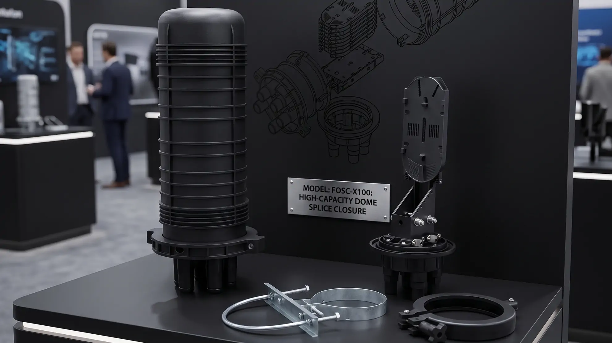
The two body styles are often called dome and inline, or vertical and horizontal. They do the same job — protect splices — but they handle cable routing and installation differently. Neither is universally better. The right choice depends on the installation scenario.
| Parameter | Dome (Vertical) | Inline (Horizontal) |
|---|---|---|
| Shape | Round or oval, cables enter from the bottom | Elongated rectangle, cables enter from both ends |
| Cable pass-through | Not inherent — cables enter and exit through the same face | Inline pass-through possible — cable enters one end, exits the other |
| Typical cable entry ports | 2 to 4 pairs (4–8 ports total) | 2 to 3 pairs (4–6 ports total) |
| Pole mounting | Natural fit — vertical orientation matches pole geometry | Requires bracket — horizontal body needs wider mounting hardware |
| Duct / handhole placement | Takes more vertical space, better in deep handholes | Slides into narrow ducts, lower profile in shallow handholes |
| Capacity range | 48–288 fibers (Jergeo JFSC-T series) | 96–144 fibers (Jergeo JFSC-L series) |
| Best suited for | Aerial, high-capacity backbone joints | Duct, underground, straight-through cable runs |
The Jergeo JFSC-T48A dome splice closure (410×170×77mm, 1.87 kg) handles smaller aerial jobs — a 48-fiber joint on a distribution pole with two cable entries in and two out, accepting cables from Φ10 to Φ14mm. For larger aerial or high-fiber backbone joints, the JFSC-T288A scales up to 288 fibers with 8 cable ports (4 in / 4 out) accepting cables up to Φ23mm in a PP+GF reinforced body.
On the inline side, the JFSC-L144B offers 3 inlet + 3 outlet ports in a 510×250×200mm PC body — a common configuration for underground duct runs where the main cable enters one end, branches to two cables at the other, and a third pair taps a lateral route. The JFSC-L144C takes 5 cable ports in a slimmer 530×205mm PP body with heat-shrink sealing, suited for installations where a permanent seal is preferred.
Capacity selection: matching fibers to the right enclosure
Fiber closure capacity is measured by the number of fusion splice protection sleeves it can hold. Common capacity tiers:
- 48 fibers: small distribution spurs, FTTH drop-point joints. The JFSC-T48A holds 48 splice sleeves across 2 splice trays (24 cores per tray max).
- 96 fibers: mid-capacity distribution nodes. Available in both form factors — the inline JFSC-L96A (440×220×180mm, 1.3–1.4 kg) and the dome JFSC-T96A (460×175×115mm, 2.3 kg).
- 144 fibers: the workhorse for backbone and feeder cable joints. Jergeo offers four different 144-core fiber optic splice closure models (JFSC-L144A, JFSC-L144B, JFSC-L144C, JFSC-L144E) with different sealing methods and port configurations.
- 288 fibers: high-density backbone joints for FTTx aggregation points. The JFSC-T288A holds 288 sleeves across 6 trays (48 cores per tray max) — the highest capacity in the JFSC series.
A practical rule: don't spec to 100% capacity. If you're splicing a 96-fiber cable, the 96-port enclosure will work, but if there's any chance of fiber count growth or you need to store extra slack, move up to 144. Splice trays bend fibers — overcrowding increases macrobend loss and makes future re-entry work harder.
Sealing methods: silicone rubber, self-adhesive, and melt glue
The seal is the most critical part of any fiber optic enclosure. Water ingress destroys splice joints. Three sealing approaches appear across the JFSC product line:
Silicone rubber gasket — Used in the JFSC-L144A and JFSC-L144B. A pre-formed silicone gasket sits between the body and the cover, compressed when the clamp band is tightened. This is a mechanical seal: it requires no heat, no special tools, and can be opened and re-sealed multiple times. Silicone maintains elasticity from −40°C to +65°C, matching the JFSC series' full working temperature range.
Self-adhesive rubber tape — Used in the JFSC-L144E, JFSC-L96A, and all vertical (dome) models. A butyl or EPDM-based adhesive tape is wrapped around the body-cover joint during closure. It conforms to irregular surfaces and fills gaps well. The self-adhesive approach is lighter — the JFSC-L144E weighs only 2.4–2.5 kg compared to the gasketed JFSC-L144A at 3.1 kg — and is common in aerial installations where weight matters on every pole.
Melt glue (heat-shrink sealing) — Used in the JFSC-L144C. A thermoplastic adhesive ring is heated with a heat gun during installation, melting and flowing into the gap between body and cover. Once cooled, it forms a rigid, highly reliable seal. The trade-off: re-entry requires cutting through the glue and applying a new ring. This method suits permanent joints that rarely need opening — for example, sealed underground joints in duct banks that are only accessed during fault repair.
IP68 rating and environmental protection
Every Jergeo JFSC model carries an IP68 protection rating. The two digits mean:
- 6 (first digit): complete protection against dust ingress — no particles can enter the enclosure
- 8 (second digit): protection against continuous water immersion beyond 1 meter depth (exact depth and duration specified by the manufacturer)
IP68 is the standard requirement for any outdoor fiber optic enclosure. It covers aerial exposure to rain and condensation, underground submersion in water-filled handholes, and direct burial in wet soil. The JFSC series operating temperature of −40°C to +65°C and relative humidity tolerance of ≤85% at 30°C means these closures can operate across most climate zones without additional environmental enclosures.
Body material matters for long-term UV and impact resistance. The JFSC-L series uses PC (polycarbonate) or PP (polypropylene). PC offers higher impact resistance — useful in areas prone to vandalism or falling debris. PP is lighter and chemical-resistant. The JFSC-T288A uses PP+GF (glass fiber reinforced PP) for the 288-port dome, where the glass fiber reinforcement adds rigidity to the larger body.
Cable entry: port count and diameter range
The number of cable entry ports determines how many cables can enter the enclosure and where they route. More ports give more flexibility but add weight and potential leak points. Here's how the JFSC series breaks down:
| Model | Type | Cable Ports | Cable Diameter | Seal Type |
|---|---|---|---|---|
| JFSC-T48A | Dome | 4 (2 in / 2 out) | Φ10–14mm | Self-adhesive |
| JFSC-T96A | Dome | 4 (2 in / 2 out) | Φ10–22mm | Self-adhesive |
| JFSC-T288A | Dome | 8 (4 in / 4 out) | Φ4–23mm | Self-adhesive |
| JFSC-L96A | Inline | 6 | Φ4–20mm | Self-adhesive |
| JFSC-L144A | Inline | 4 (2 in / 2 out) | Φ7–22mm | Silicone rubber |
| JFSC-L144B | Inline | 6 (3 in / 3 out) | Φ7–22mm | Silicone rubber |
| JFSC-L144C | Inline | 5 | Φ4–20mm | Melt glue |
| JFSC-L144E | Inline | 6 | Φ4–20mm | Self-adhesive |
The cable diameter range matters for adapter selection. Each port uses a heat-shrink boot or mechanical adapter that must match the actual cable outer diameter. A Φ7–22mm range (JFSC-L144A/B) covers most standard loose-tube and armored cables. The wider Φ4–23mm range on models like the JFSC-T288A accommodates everything from micro-cables to large armored feeders.
Inline models with separate inlet/outlet pairs (JFSC-L144A: 2+2, JFSC-L144B: 3+3) naturally support straight-through cable routing — the main cable enters one end and exits the other, with branch cables tapping at the sides. Models with undifferentiated ports (JFSC-L144C: 5, JFSC-L144E: 6, JFSC-L96A: 6) offer more routing flexibility but require more careful planning of which cable goes where.
Re-entry capability and field maintenance
Not every splice joint stays sealed forever. Network upgrades, fault repairs, and route reconfigurations all require opening the fiber enclosure and getting back inside. The sealing method directly determines re-entry difficulty:
- Silicone rubber gasket (JFSC-L144A, JFSC-L144B): Loosen the clamp band, lift the cover, work on the trays, replace the cover, retighten. The gasket compresses back into shape. Re-seal is reliable for multiple cycles. Best choice for joints that may need regular access.
- Self-adhesive tape (JFSC-T48A, JFSC-T96A, JFSC-T288A, JFSC-L96A, JFSC-L144E): Cut the tape, open, work, apply new tape on re-closure. Straightforward but requires carrying replacement tape to every visit. Commonly used in aerial work where weight savings offset the minor re-entry inconvenience.
- Melt glue (JFSC-L144C): Cut through the glue ring, work, apply a new glue ring and re-heat. Most labor-intensive re-entry, but the most permanent seal. Suitable for underground joints in stable environments that are opened rarely — perhaps once every few years during fault events.
All JFSC models are designed for reuse. The splice trays are removable — each tray holds up to 12–24 cores (model dependent) and can be lifted out on a hinge or fully removed for access to the cable entry area. Internal fiber routing follows a clean, labeled path so technicians can identify individual splice points without disturbing neighboring fibers.
How to choose the right fiber closure for your deployment
The decision comes down to four questions:
- How many fibers? Count the total splice sleeves needed. Add 20–30% spare capacity for future growth or repair splices. A 72-fiber cable run should use a 96-port minimum enclosure.
- How is it mounted? Pole or aerial → dome (vertical). Duct, handhole, or buried → inline (horizontal). Both types support all three mounting methods (aerial/duct/underground), but the physical shape favors one over the other.
- How often will it be opened? Frequent re-entry → silicone rubber gasket. Rare access → melt glue. Aerial weight-sensitive → self-adhesive tape.
- How many cables converge? Two cable segments meeting in a straight line need 2 ports minimum. Three-way branches need 3+ ports. Complex junctions with 5–8 cables need enclosures with matching port counts — the JFSC-T288A with 8 ports or the JFSC-L144C with 5 ports handle these cases.
Related Products
References
- IEC 61753 — fiber optic interconnecting devices and passive components performance standards
- FOA Splice Guide — The Fiber Optic Association reference on fiber splicing methods and closures
Key Takeaway
Match the fiber closure to the physical environment first (dome for aerial, inline for duct), then size by fiber count with 20–30% spare capacity, then choose the sealing method based on expected re-entry frequency. A 144-core fiber optic splice closure with silicone rubber gasket sealing covers the majority of backbone and feeder cable joint scenarios. For high-fiber aggregation points, step up to a 288-port dome closure with PP+GF reinforcement.
Related products
Related Articles

How to Install Splice Trays in an FDC
Step-by-step field guide for installing splice trays — applies to both closures and cabinets.
Read Article →
Fiber Optic Splitter Guide
PLC splitter types, ratios, and selection criteria for FTTx network design.
Read Article →
Fiber Distribution Cabinet Buying Guide
How to spec the outdoor cabinet that houses your splice closures and distribution modules.
Read Article →